Rotor bearing for a wind power generating plant

a technology of rotating bearings and wind power generating plants, which is applied in the direction of elastic bearings, machines/engines, mechanical equipment, etc., can solve the problems of undesirably high biases in the axial rows, the axial clearance of triple-row roller bearings is relatively narrow, and the axial clearance of roller bearings is much more sensitive than that of ball bearings, etc., to achieve advantageous effect on the smooth operation of bearings and reduce the hardness gap

Active Publication Date: 2014-01-23
IMO HOLDING GMBH
View PDF11 Cites 10 Cited by
  • Summary
  • Abstract
  • Description
  • Claims
  • Application Information

AI Technical Summary

Benefits of technology

[0033]The raceways of large slewing bearings are typically hardened, particularly inductively hardened. This can also be done with the raceway ring according to the invention. Due to process limitations, there is a narrow spot at which the hardness is reduced between the beginning and the end of a raceway hardened in the forward-feed process. This so-called hardness gap can be lowered with respect to the rest of the particular raceway by abrasive grinding, so the rolling elements rolling over it do not transmit a load at that location. If the raceways and the intermediate ring are inductively hardened gaplessly by a special method that requires at least two induction heads, then there is no hardness gap and no need to abrasively grind the raceway, which has an advantageous effect on the smoothness of operation of the bearing.

Problems solved by technology

Triple-row roller bearings have a relatively narrow axial clearance, however, which is troublesome particularly in wind turbine applications.
Furthermore, roller bearings are much more sensitive than ball bearings to standstill vibrations.
The axial play of the bearing can be narrowed further by the bolt clamping forces exerted on the bearing rings by the fastening bolts, and undesirably high biases can occur in the axial rows if the ring geometry is unfavorable.
With rotor bearings several meters in diameter, such adjustment and fine-tuning of play is very labor-intensive, and even relatively small changes in environmental conditions, e.g. temperature changes, can disrupt the sensitive balance struck between freedom from play and moderate bias.
For example, load situations can actually arise where an axial row is largely or completely load-free, and the rolling elements in that row do not roll sufficiently or even stand still.
In this case, the rolling elements drag over the raceway and the worrisome phenomenon of flat wear can develop, particularly in the form of abrasions.

Method used


Image

  • Rotor bearing for a wind power generating plant
  • Rotor bearing for a wind power generating plant
  • Rotor bearing for a wind power generating plant

Examples


Embodiment Construction

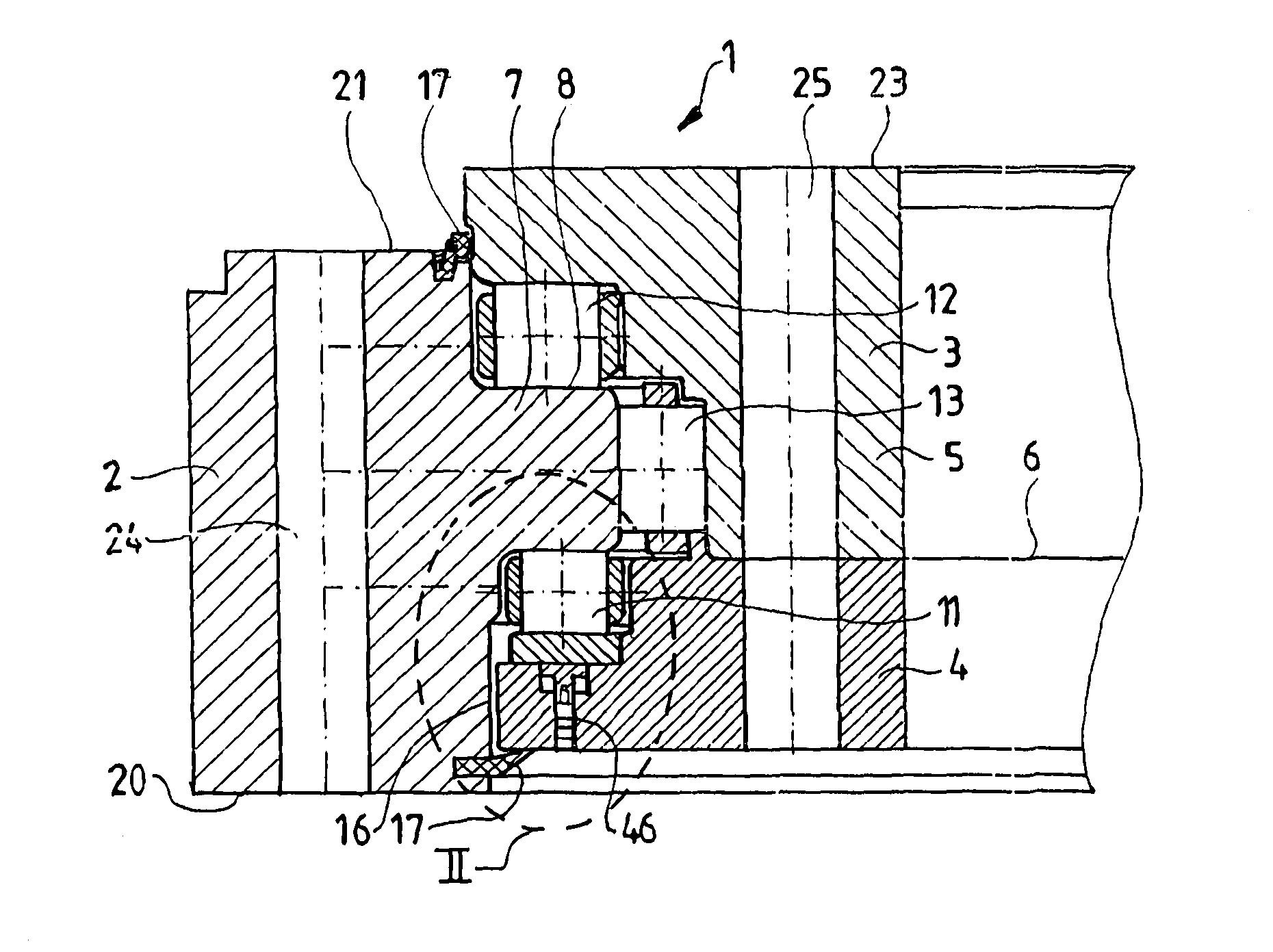
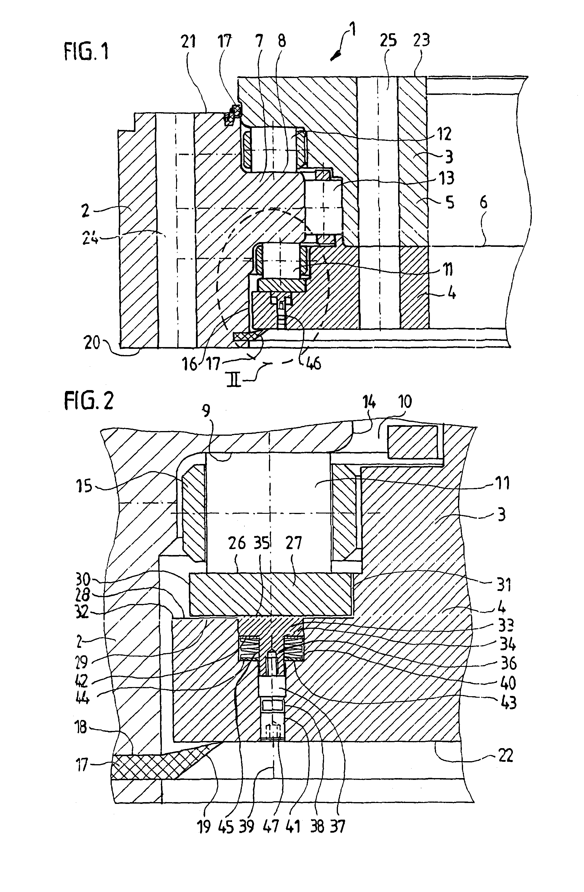
[0039]FIG. 1 is a section taken transversely through an annular rolling bearing 1 according to the invention. This is a large rolling bearing, of the kind used, for example, in wind power generating plants, for example as the rotor bearing or main bearing thereof. Clearly, similar designs could also be used for other purposes: for example, as the blade bearings or the yaw or nacelle bearing of a wind power generating plant.

[0040]In the case illustrated, the viewer will recognize an outer ring 2 configured as a nose ring and, disposed concentrically therein, an inner ring 3, which is preferably divided into two subrings 4, 5 abutting each other along a plane 6. The ring 3 formed by these adjoining subrings 4, 5 has an approximately C-shaped cross section and surrounds the nose or a circumferential flange 7 of the nose ring 2 on the top and bottom surfaces 8, 9 thereof with a gap 10, such that the two rings 2, 3 can be rotated in mutually opposite directions.

[0041]In the exemplary emb...


PUM


Abstract

A rolling bearing, particularly a rotor bearing, or main bearing, for a wind power generating plant, the bearing having at least two mutually concentric rings separated from each other by a gap in which one or more rows of rolling elements roll along raceways on both rings, such that the two rings are rotatable in mutually opposite directions about their common axis, wherein each ring has at least one connection surface for connection to a foundation, wherein the connection surfaces extend parallel to one another and are passed through approximately perpendicularly by a plurality of fastening bores for receiving fastening bolts extending through them or screwed into them, wherein the raceway of at least one rolling-element row is formed on a part separate from the ring concerned and is pushed away from the ring concerned in a direction perpendicular to the connection surfaces, by at least one resilient element.

Description

BACKGROUND OF THE INVENTION[0001]1. Field of the Invention[0002]The invention is directed to a rolling bearing, particularly a rotor bearing or main bearing for a wind power generating plant, having at least two mutually concentric rings that are separated from each other by a gap in which one or more rows of rolling elements roll along raceways on both rings, such that the two rings can be rotated in mutually opposite directions about their common axis, wherein each ring has at least one planar, annular, preferably raised connection surface for connection to a machine part, plant part, chassis or foundation, wherein the connection surfaces extend parallel to one another and are passed through approximately perpendicularly by a plurality of fastening bores for receiving fastening bolts that are inserted all the way through them or screwed into them.[0003]2. Description of the Prior Art[0004]Since larger machines and plants are generally more advantageous commercially than smaller on...

Claims


Application Information

Patent Timeline
Patent Type & Authority Applications(United States)
IPC IPC(8): F03D11/00
CPCF03D11/0008F16C19/381F16C25/08F16C25/083F16C27/08F16C33/60F16C2300/14F16C2360/31F03D80/70Y02E10/72
Inventor FRANK, HUBERTUS
Owner IMO HOLDING GMBH
Why Eureka
Try Eureka