Power tool with an eccentrically driven working tool

Active Publication Date: 2006-03-30
HILTI AG
View PDF4 Cites 11 Cited by
  • Summary
  • Abstract
  • Description
  • Claims
  • Application Information

AI Technical Summary

Benefits of technology

[0013] Advantageously, the pivot device includes a spring arrangement for preloading the roller pairs together. Thereby, additional costs, which are associated with preloading of the roller pairs, can be minimized. In addition, less additional mounting space is necessary.
[0014] Alternatively, the roller pairs can be preloaded by separate spring elements. Thereby, the wear of one roller pair can be compensated independently from the wear of another roller pair. Thereby, an almost exact guidance of the working tool during the tool entire service life can be maintained even in the case of different wear of guide rollers and the drive and counter-pressure rollers.
[0015] Advantageously, the pivot device has actuation means for bringing the roller pairs together into the release position. Thereby, a particularly comfortable and rapid replacement of the working tool becomes possible.
[0016] It is particularly advantageous when the actuation means is retainable in the release position. This further simplifies handling of the working tool replacement.
[0017] According to a particularl

Problems solved by technology

A drawback of the known power tool consists in that with the guide rollers being fixedly secured on the blade housing, wear of the guide rollers, which increases during their service life, cannot be compensated.
As a result, the precision of the working tool guidanc

Method used


Image

  • Power tool with an eccentrically driven working tool
  • Power tool with an eccentrically driven working tool
  • Power tool with an eccentrically driven working tool

Examples


Embodiment Construction

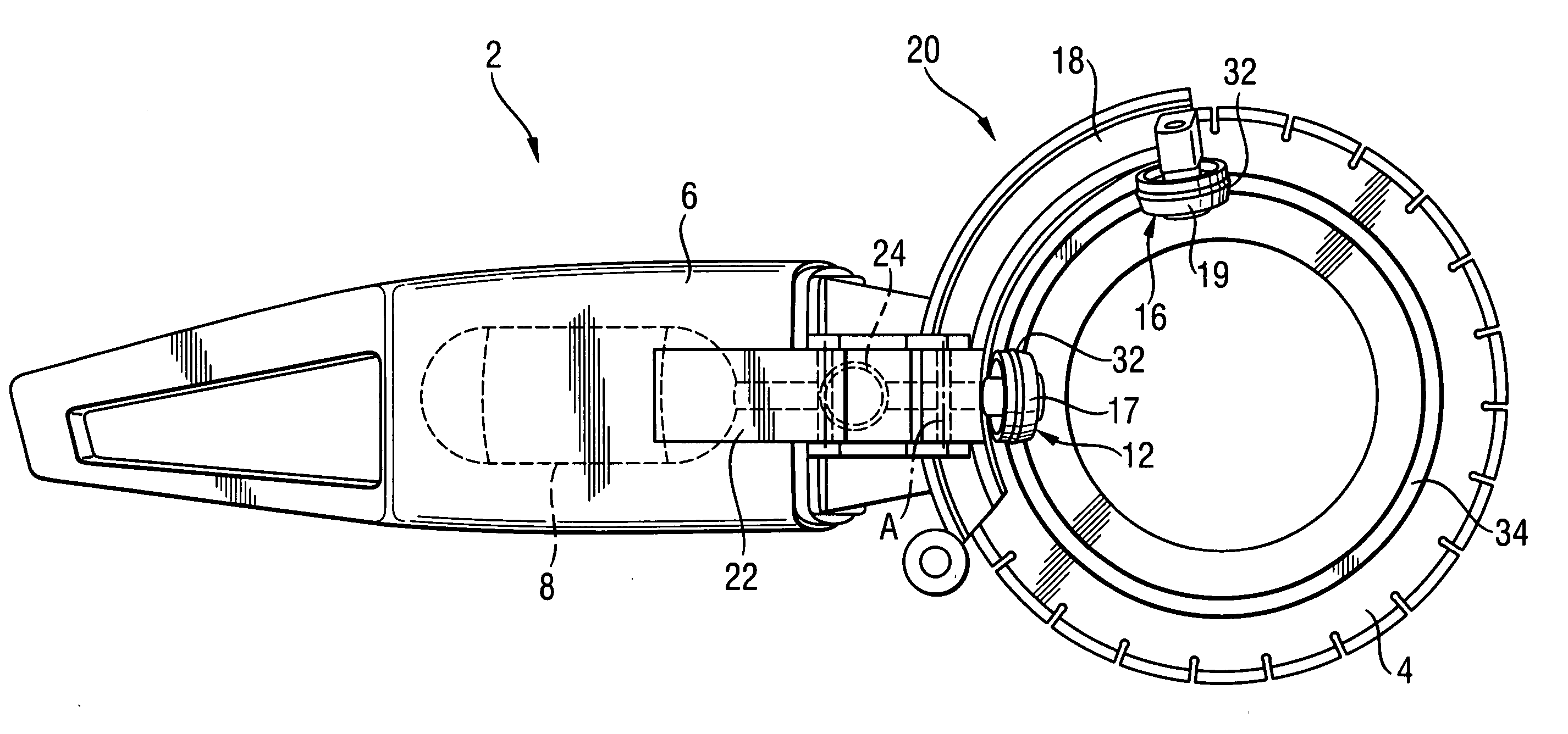
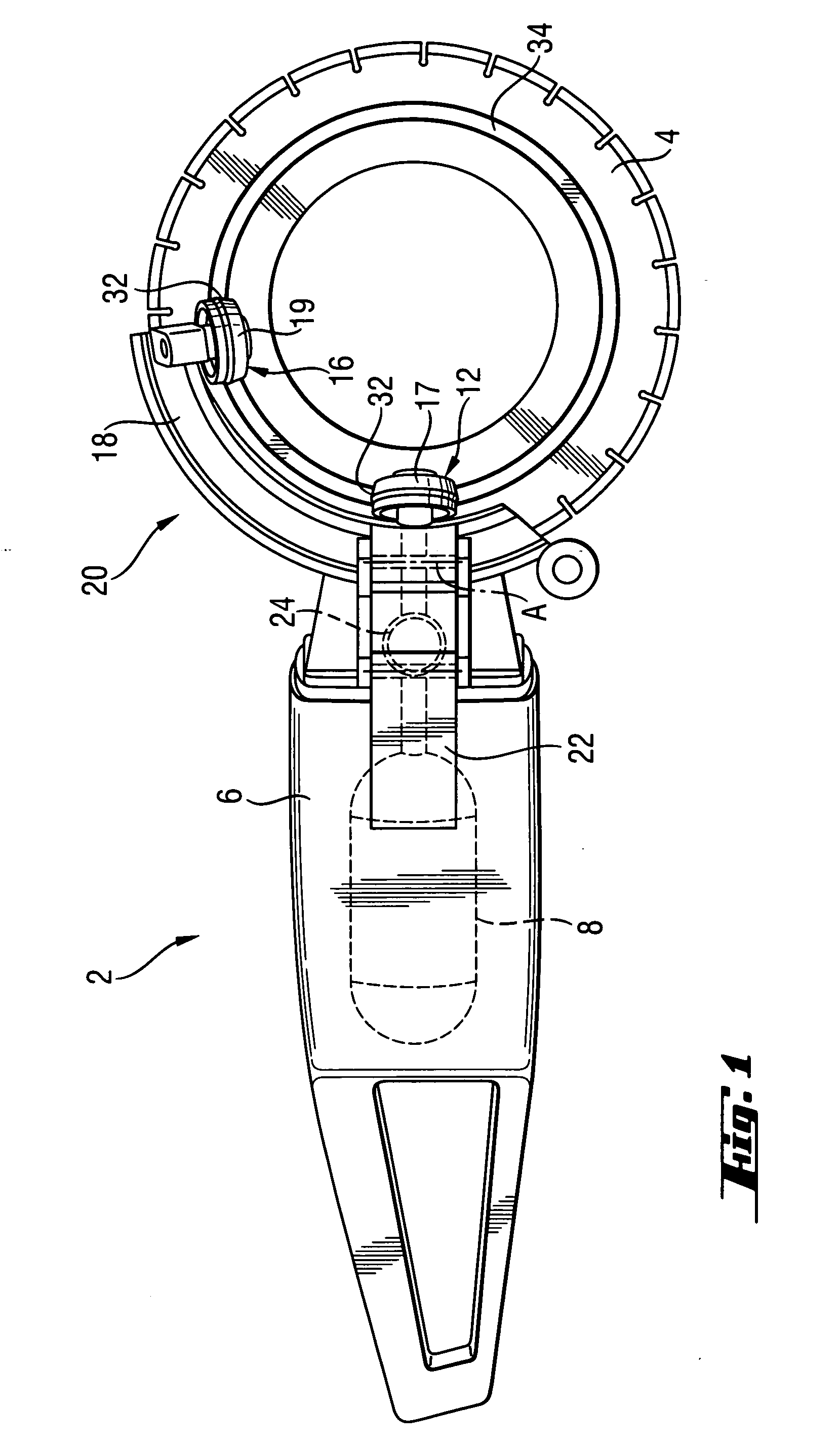
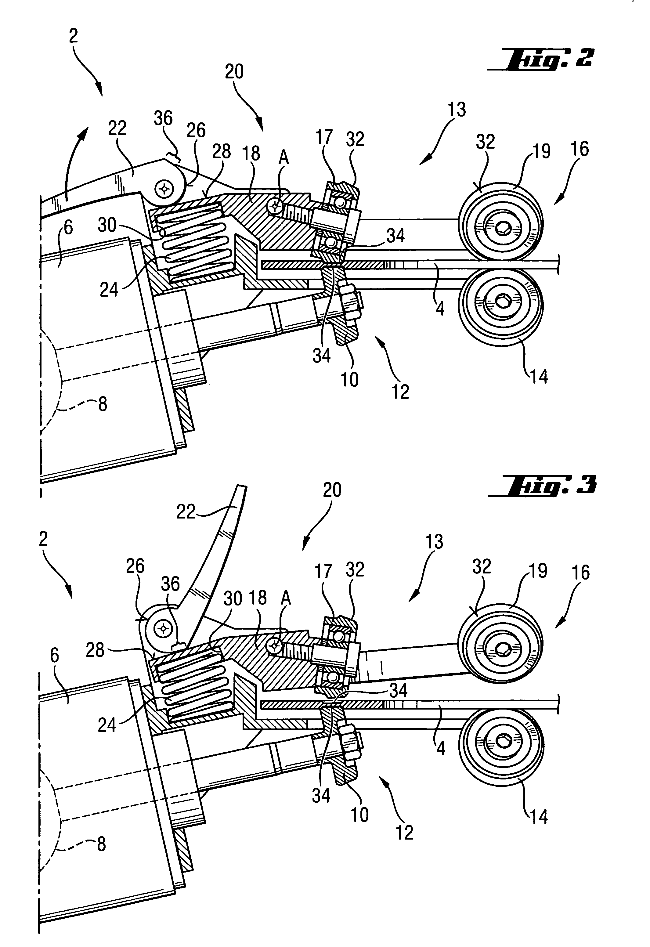
[0027] A power tool 2 according to the present invention, which is shown in FIG. 1, is formed as a circular saw with a circular working tool 4 in form of a disc that is eccentrically driven. The power tool 2 includes a housing 6, a motor 8 located in the housing 6 and rotatably connected with a first drive roller 10, which is formed as a friction wheel, of a drive roller pair 12 of a roller device designated generally with a reference numeral 13, as shown in FIG. 2.

[0028] As shown in FIGS. 2-3, the first drive roller 10 is fixedly supported on the housing 6 a spaced relationship to a guide roller 14 of a guide roller pair 16. A second drive roller 17 of the drive roller pair 12, which is formed as a counter-pressure roller, is rotatably supported, together with a second guide roller 19 of the guide roller pair 16, on a support member 18 of a pivot device 20. The support member 18 is supported on the housing 6 for a pivotal movement about a pivot axis A. The pivot device 20 also inc...


PUM


Abstract

A power tool, in particular a circular saw, for eccentrically a rotatable working tool and, in particular, a circular saw blade, includes a roller device (13) supported on a tool housing (6) and having at least two roller pairs (12, 16) each having a first roller (10, 14) and a second roller (17, 19) engageable with opposite sides of the working tool (4), with at least one of the rollers (10, 14, 17, 19) of at least one roller pair (12, 16) being rotatable by a tool motor (8) which is located in the housing (6), for driving the working tool (4), and a pivot device (20) for pivoting the first rollers (10, 14) together relative to the second rollers (17, 19) between a release position in which the working tool (4) is brought in or removed from the roller device (13), and a drive position in which a forcelocking connection between the at least one of the rollers (10) of the at least one roller pair (12, 16) and the working tool (4) is established.

Description

BACKGROUND OF THE INVENTION [0001] 1. Field of the Invention [0002] The present invention relates to a power tool, in particular, a circular saw with an eccentrically driven working tool, in particular, a circular saw blade. The power tool includes a housing and a motor located in the housing. The power tool further includes a roller device supported on the housing and having at least two roller pairs spaced from each other and each having a first roller and a second roller. The first and second rollers of both roller pairs engage opposite sides of the working tool. At least one of the rollers of at least one roller pair is rotatable by the motor for driving the working tool. [0003] 2. Description of the Prior Art [0004] In power tools of the type described above, as a rule, one roller pair is used for driving the working tool, with the working tool being clamped between one roller, which functions as a drive roller, and another, counter-pressure roller. The at least one another rol...

Claims


Application Information

Patent Timeline
IPC IPC(8): B27B9/00
CPCB23D47/123Y10T83/9403
Inventor BLATZ, THOMAS
Owner HILTI AG
Why Eureka
Try Eureka