
Imaging apparatus, imaging apparatus body, and shading correcting method

a technology of imaging apparatus and shading, applied in the field of shading correcting methods, can solve problems such as image quality degradation, and achieve the effect of reducing the burden on the storage capacity therefor

Inactive Publication Date: 2013-10-22
FUJIFILM CORP
View PDF13 Cites 4 Cited by
  • Summary
  • Abstract
  • Description
  • Claims
  • Application Information

AI Technical Summary

Benefits of technology

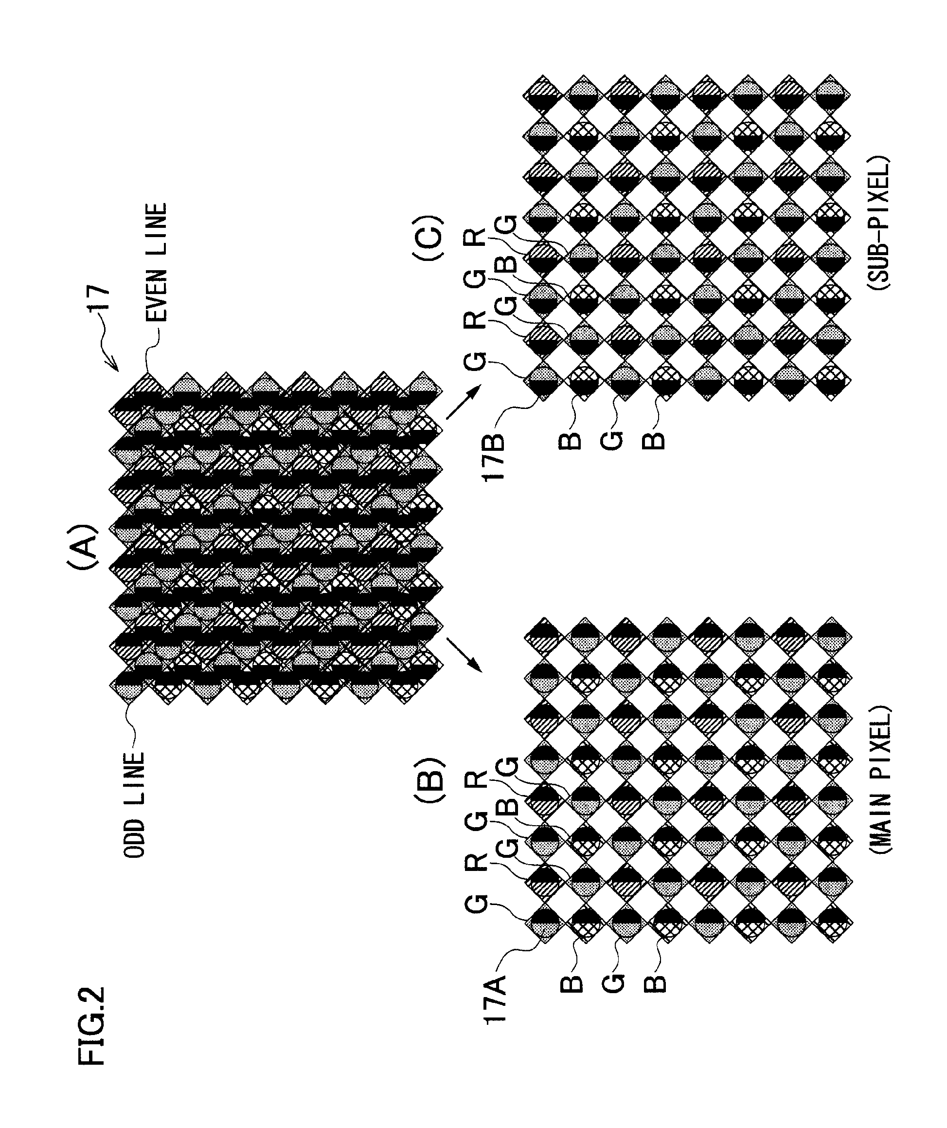
[0021]According to the present invention, if a correction table corresponding to a mounted imaging unit is stored, one-dimensional shading occurring in a disparity direction in a main image / sub-image is corrected using the correction table. Every time the same imaging unit as the previous one is mounted, therefore, processing for determining the correction table is omitted.
[0022]If the correction table corresponding to the mounted imaging unit is not stored, a correction table corresponding to a set photographing condition is calculated and stored. If the imaging unit is mounted after that, the shading of the main image / sub-image is corrected using a correction table corresponding to the imaging unit.
[0023]Since the shading is one-dimensional, a parameter stored in the correction table for each imaging unit may be a one-dimensional value. A burden on a storage capacity therefor is smaller than that when a correction table storing a two-dimensional parameter is stored.

Problems solved by technology

As a result, luminance shading, which causes a light-dark strain because brightness is not uniform depending on a position of the imaging plane, occurs in an imaging signal output from the image sensor, resulting in a deteriorated image quality.

Method used


Image

  • Imaging apparatus, imaging apparatus body, and shading correcting method
  • Imaging apparatus, imaging apparatus body, and shading correcting method
  • Imaging apparatus, imaging apparatus body, and shading correcting method

Examples


first embodiment

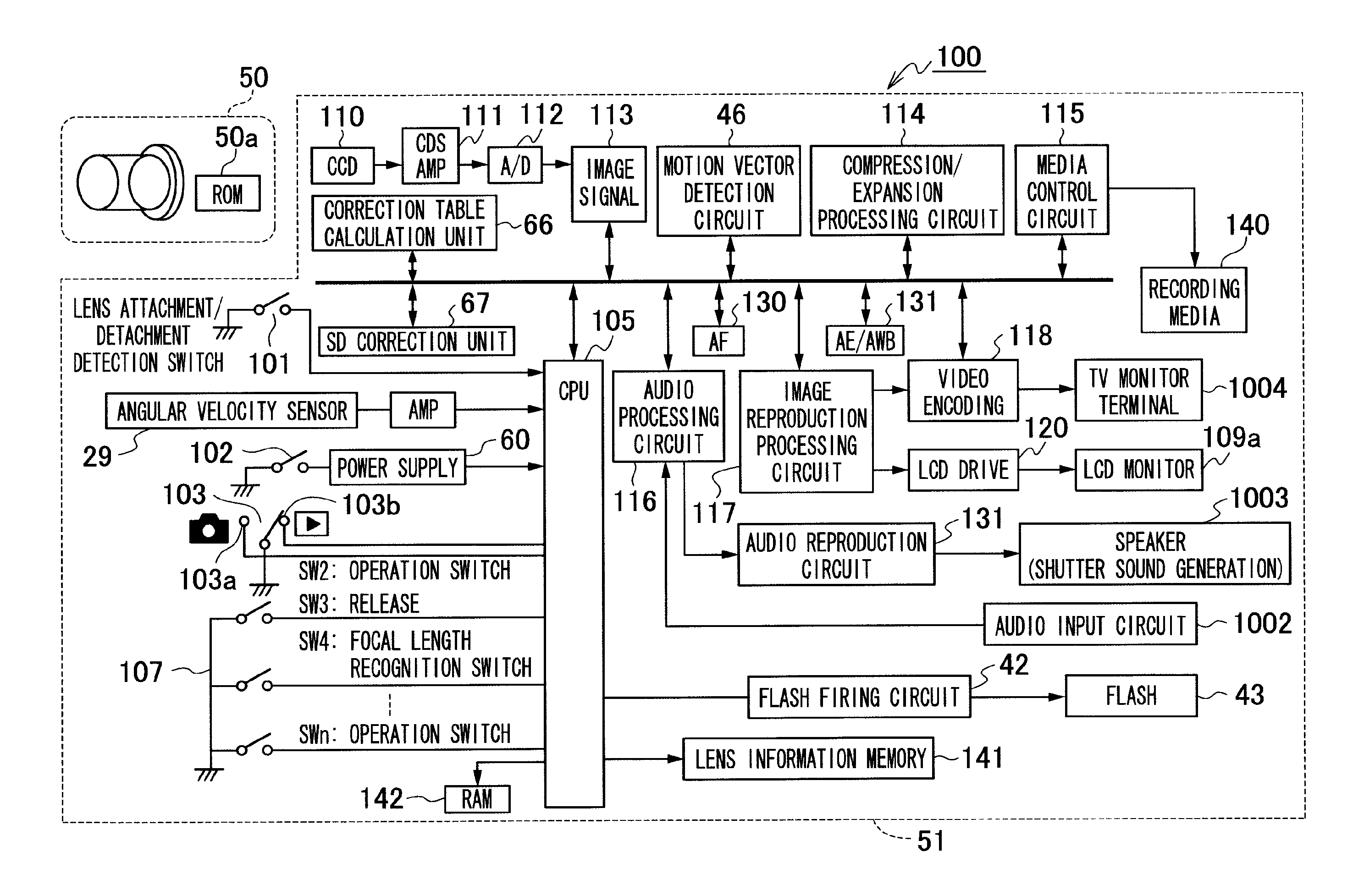
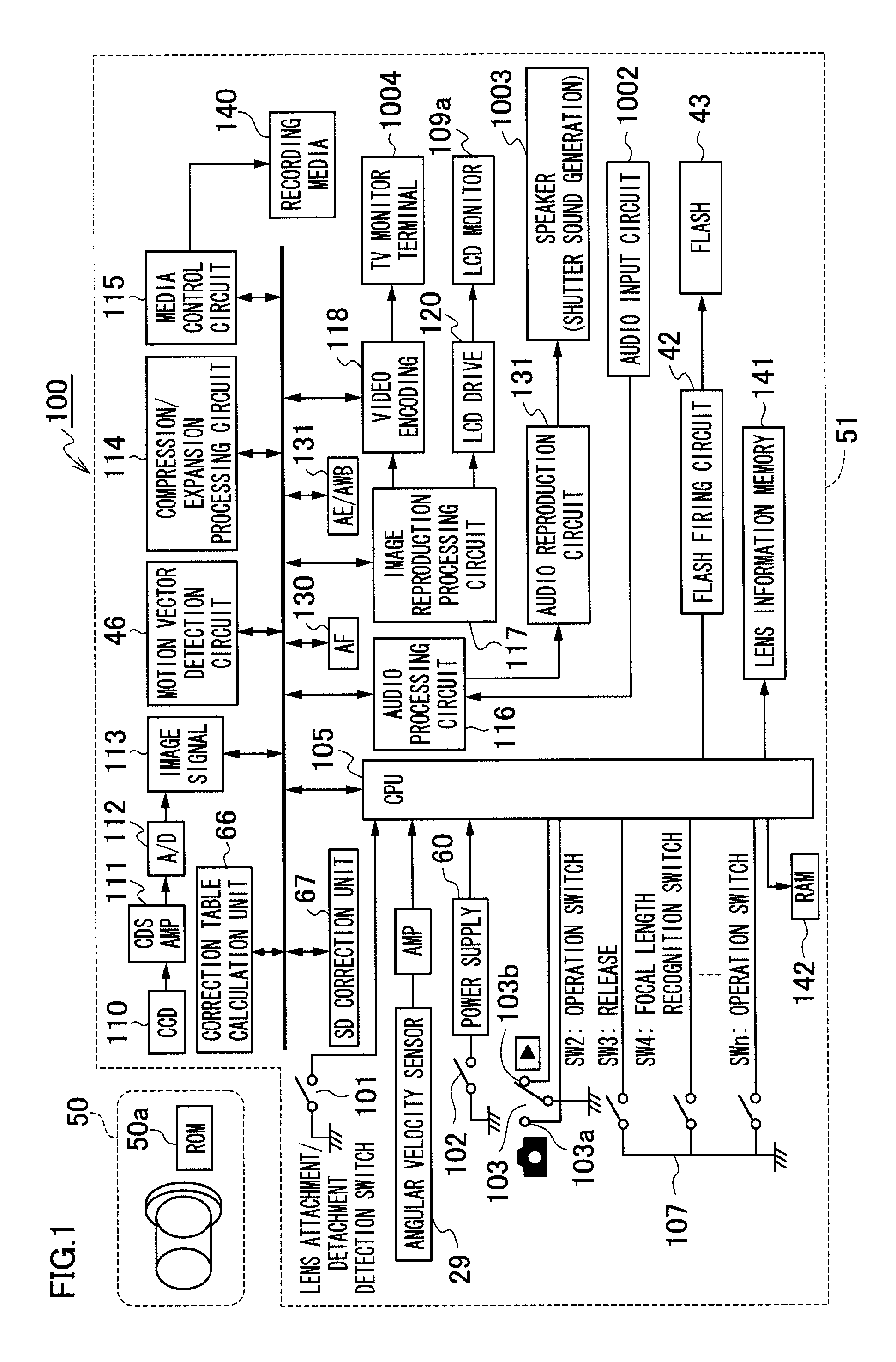
[0032]FIG. 1 is a block diagram illustrating a configuration of a digital camera 100 according to a first embodiment. The digital camera 100 includes an interchangeable lens unit 50 and a camera body 51.

[0033]The lens unit 50 can be mounted on the camera body 51 directly or via a mount converter. The lens unit 50 includes a lens ROM 50a serving as a storage medium containing lens information. The lens information can include identification information specific to the lens unit 50, firmware relating to processing for driving control for making an imaging optical system including a zoom lens, a focus lens, a diaphragm, a shutter, and their driving system, an image stabilization device, and other functions, which are included in the lens unit 50, effectively function in the camera body 51, and numerical information (a setting parameter) relating to the driving control.

[0034]A plurality of lens units 50, which can be mounted on the camera body 51, exists, and is a mixture of one that re...


PUM


Abstract

An imaging apparatus body on which a lens unit including an imaging optical system and an identification information storage unit that stores specific identification information can be removably mounted, comprising a shading correction unit that corrects, when the determination unit determines that the correction table corresponding to the identification information of the mounted lens unit is stored in the correction table storage unit, the shading in the set of viewpoint images according to the correction table, corresponding to the identification information of the mounted lens unit, stored in the correction table storage unit.

Description

[0001]This application is a continuation application and claims the priority benefit under 35 U.S.C. §120 of PCT Application No. PCT / JP2011 / 078389 filed on Dec. 8, 2011 which application designates the U.S., and also claims the priority benefit under 35 U.S.C. §119 of Japanese Patent Applications No. 2011-029854 filed on Feb. 15, 2011, which applications are all hereby incorporated in their entireties by reference.TECHNICAL FIELD[0002]The present invention relates to a technique for respectively focusing subject images, which have passed through different areas in two directions of a photographic lens, on an image sensor, to acquire different viewpoint images. Particularly, the present invention relates to a technique for correcting shading occurring in the viewpoint images.BACKGROUND ART[0003]As discussed in Patent Document 1, a light flux incident on an image sensor from an imaging lens includes a large number of components of light focused in an oblique direction in addition to c...

Claims


Application Information

Patent Timeline
Patent Type & Authority Patents(United States)
IPC IPC(8): H04N5/228H04N9/73H04N5/232
CPCG03B17/14H04N13/0022H04N13/0025H04N13/0217H04N5/23209H04N5/3572H04N5/3696G03B2206/00H04N13/218H04N13/128H04N13/133H04N23/663H04N23/672H04N23/673H04N25/61H04N25/704H04N25/702H04N25/134
Inventor KURAHASHI, HIDEKAZUHASEGAWA, RYOU
Owner FUJIFILM CORP
Learn More