Weapons interface mounting device

Inactive Publication Date: 2013-10-29
BOBRO ANDREW
View PDF38 Cites 35 Cited by
  • Summary
  • Abstract
  • Description
  • Claims
  • Application Information

AI Technical Summary

Benefits of technology

[0008]It is an objective of the present invention to provide a lever-deployed clamp-driver system for incorporation into a weapon interface mounting device that is enabled by the driver system to provide extremely rapid remov

Problems solved by technology

Although some needs have been met with such prior art devices, significant performance issues remain.
In particular, manufactured rails having even slight imperfections are not well accommodated by the prior art.
They are not well secured and repeated shock due to firing can lead to degradation and eventual failure of the rail/interface system.
Although prior art devices posses an indexing system, accessories mounted us

Method used


Image

  • Weapons interface mounting device
  • Weapons interface mounting device
  • Weapons interface mounting device

Examples


Embodiment Construction

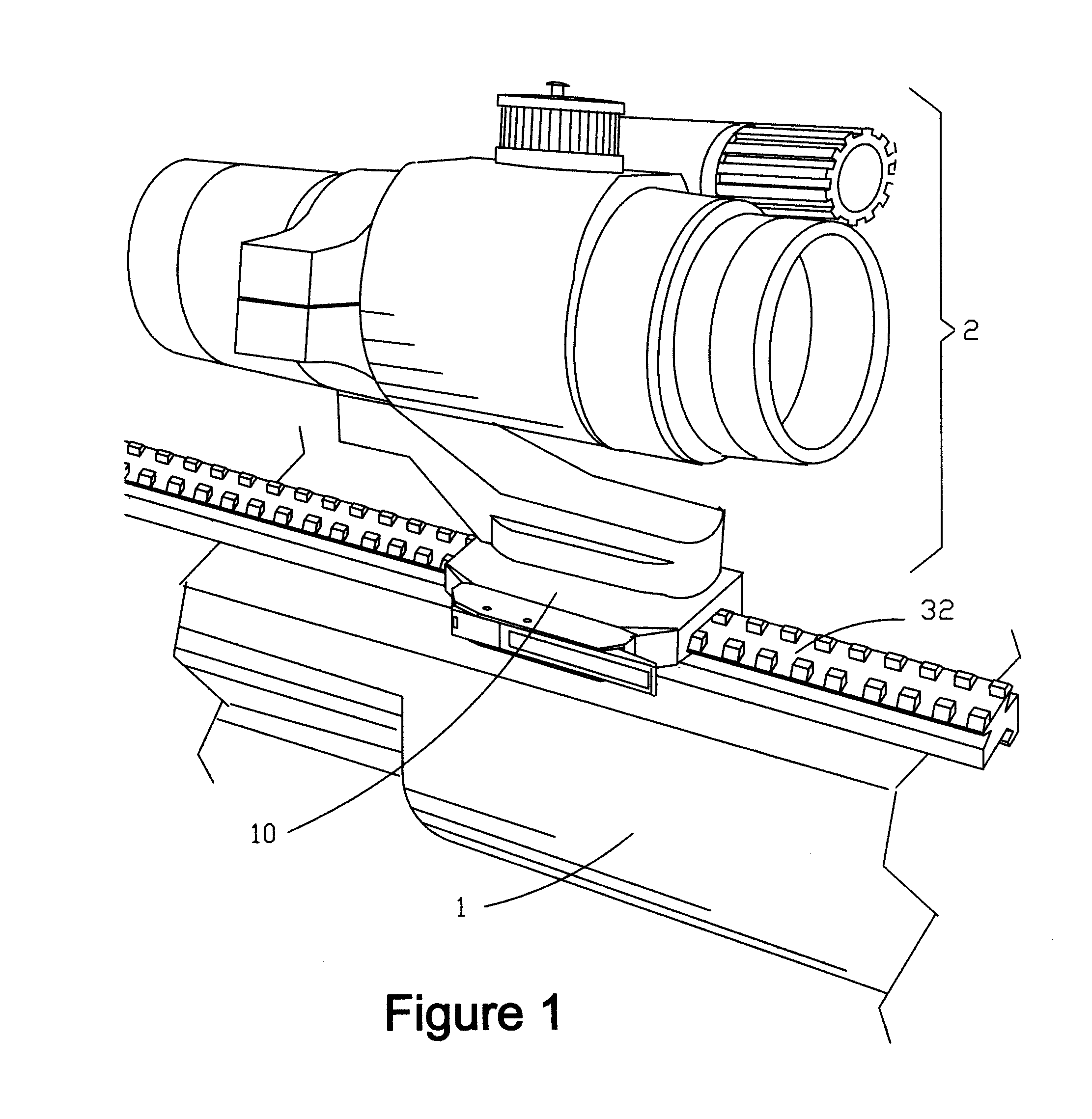
[0062]FIG. 1 shows a firearm (1) with an accessory (2) mounted thereto. The mounting apparatus consists of a MIL-STD 1913 rail (30) and the weapon interface mounting device (10) of the present invention. As shown in FIG. 8, the MIL-STD-1913 rail (30) comprises a series of ridges (31) interspersed with flat slots (33). Accessories are mounted by means of a “rail-grabber” which is clamped to the slots (33) or onto the rail (30) itself.

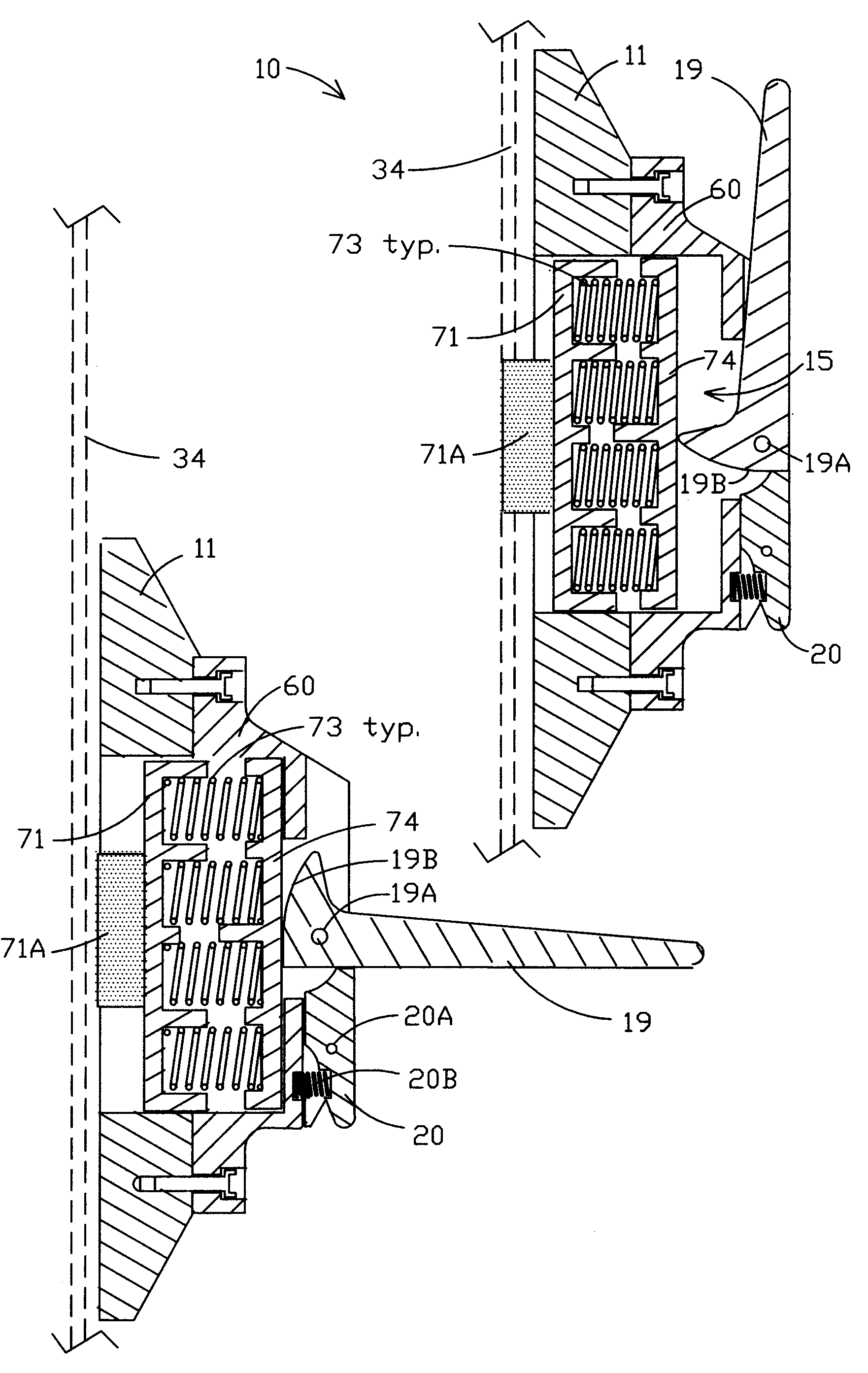
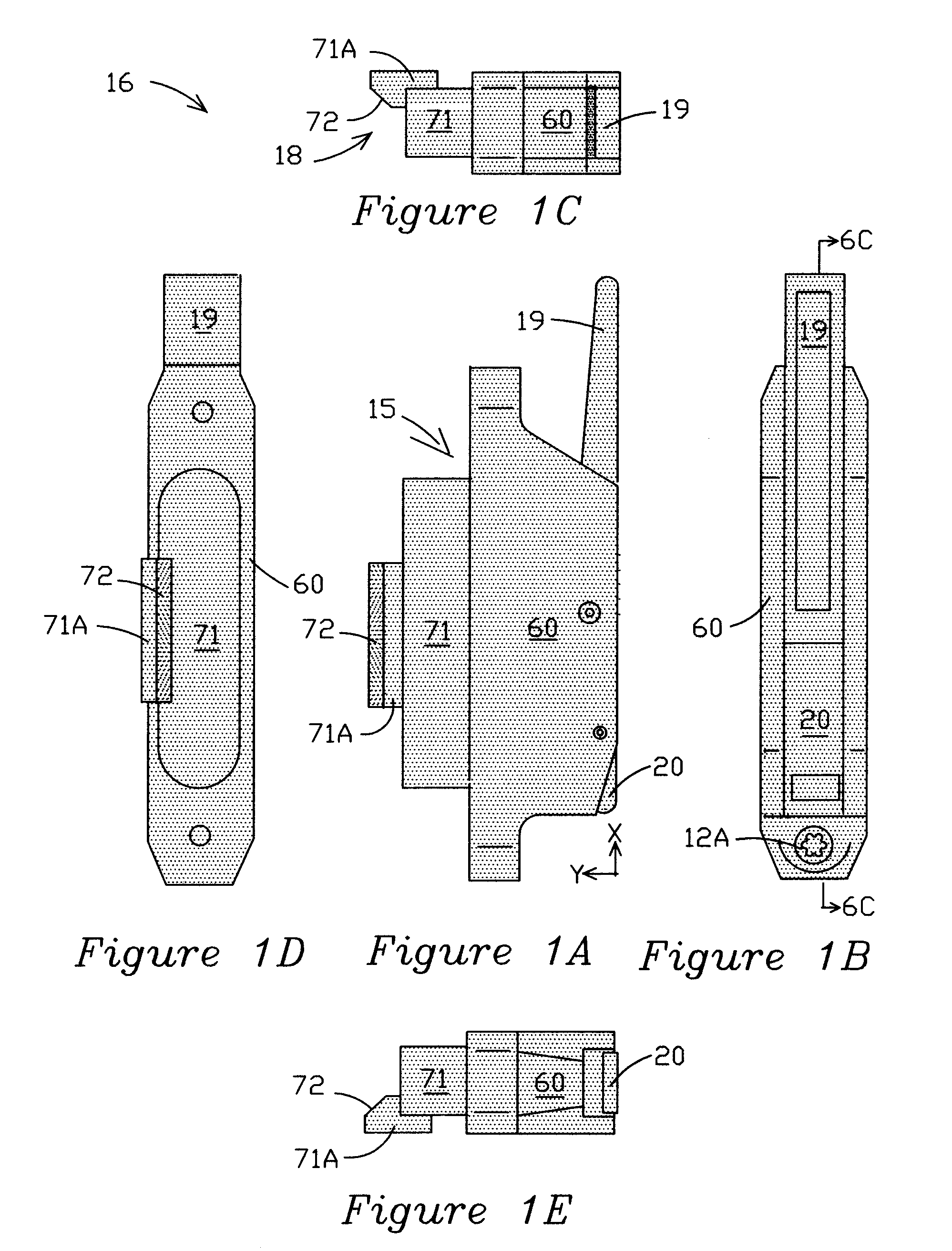
[0063]Driver system 16, shown in five orthogonal views in FIGS. 1A-E, constitutes, in a basic form of the invention, a first of two main embodiments. Driver system 16 enables user-manipulation of lever 19 to deploy an automatically-locked operational mode wherein a cam portion 19B of lever 19 transmits compressive clamping force onto a special compressible drive subassembly 15, partially enclosed in driver housing 60 and including a movable clamp-jaw 71, configured with a shaped surface 18 (FIG. 1C) for engaging and clamping a workpiece in co-operation w...


PUM


Abstract

The weapon interface mounting device is designed to permit a secure interface between a Mil-Std 1913 or similar rail and a compatible component such as an optical device, bipod, or light source. It can be easily installed, requires no adjustment by the user, and will mate securely to rails that are out of specification or poorly manufactured. The weapon interface mounting device utilizes a constant force system that applies adequate pressure to positively secure any accessory or device despite being subject to rough treatment such as recoil shock from a host weapon. Unlike prior art devices, the weapon interface mounting device insures repeatability by utilizing a mechanical index system.

Description

CROSS REFERENCE TO RELATED APPLICATIONS[0001]This application is related to and claims priority from earlier filed U.S. Provisional Patent Application No. 61 / 111,285, filed Nov. 4, 2008.FIELD OF THE INVENTION[0002]The present invention relates generally to accessory mounting assemblies for combat weapons.BACKGROUND OF THE INVENTION[0003]As the field of combat and commercial weaponry expands, numerous add-on enhancements have become available for attachment to standard firearms. For example, the well-known M16 weapon system, includes a mil-std 1913 dovetail rail extending along the top of the upper receiver. This rail provides a convenient mounting point for many types of accessories such as tactical lights, night vision devices, laser sighting modules, reflex sights, fore grips, and bipods.[0004]Field modification of weapons is critical in combat situations. As such, standardized attachment assemblies have been developed to allow quick and easy removal and mounting of accessory devi...

Claims


Application Information

Patent Timeline
IPC IPC(8): F41C27/00
CPCF41G11/003
Inventor BOBRO, ANDREW
Owner BOBRO ANDREW
Why Eureka
Try Eureka