Methods and systems for controlling transient engine response

a transient engine and response technology, applied in the direction of machines/engines, mechanical equipment, transportation and packaging, etc., can solve the problems of increasing the time for the engine to respond to the changing conditions, reducing the speed of the engine, and reducing the efficiency of the engine operation. , to achieve the effect of improving the transient response of the engine, reducing the time, and reducing the tim

Active Publication Date: 2013-10-29
GE GLOBAL SOURCING LLC
View PDF43 Cites 24 Cited by
  • Summary
  • Abstract
  • Description
  • Claims
  • Application Information

AI Technical Summary

Benefits of technology

[0005]By injecting the compressed air to an engine cylinder under conditions, such as transient conditions when engine load is increased, a more proportionate increase in air supplied to the engine may result and an air-fuel ratio may at least be maintained, for example. Further, by injecting the compressed air directly to cylinders of the engine, a time for the engine to respond to the changing conditions may be decreased. For example, the compressed air may be injected to the first cylinder in which the intake valve closes after it is determined that there is a need for additional air (e.g., during an immediately subsequent engine stroke). As such, the cylinders of the engine receive the compressed air in a reduced amount of time, thereby improving the transient response of the engine.

Problems solved by technology

As a result, during such a transient conditions, a greater amount of fuel may be injected to the engine; however, the fuel increase may not be immediately matched by a proportionate increase in air supplied to the engine.
This may result in an air-fuel ratio that is too rich, leading to a decrease in engine speed, inefficient engine operation, and / or an increase in engine emissions.
In such an example, however, there is a delay between a time a need for the additional air is determined and the time when the additional air is received by the cylinders due to, for example, a time it takes to fill the manifold with the additional air.
As such, the cylinders may not receive the additional air for several engine strokes after the storage tank begins delivering the additional air to the intake manifold, thus delaying the response of the engine.

Method used


Image

  • Methods and systems for controlling transient engine response
  • Methods and systems for controlling transient engine response
  • Methods and systems for controlling transient engine response

Examples


Embodiment Construction

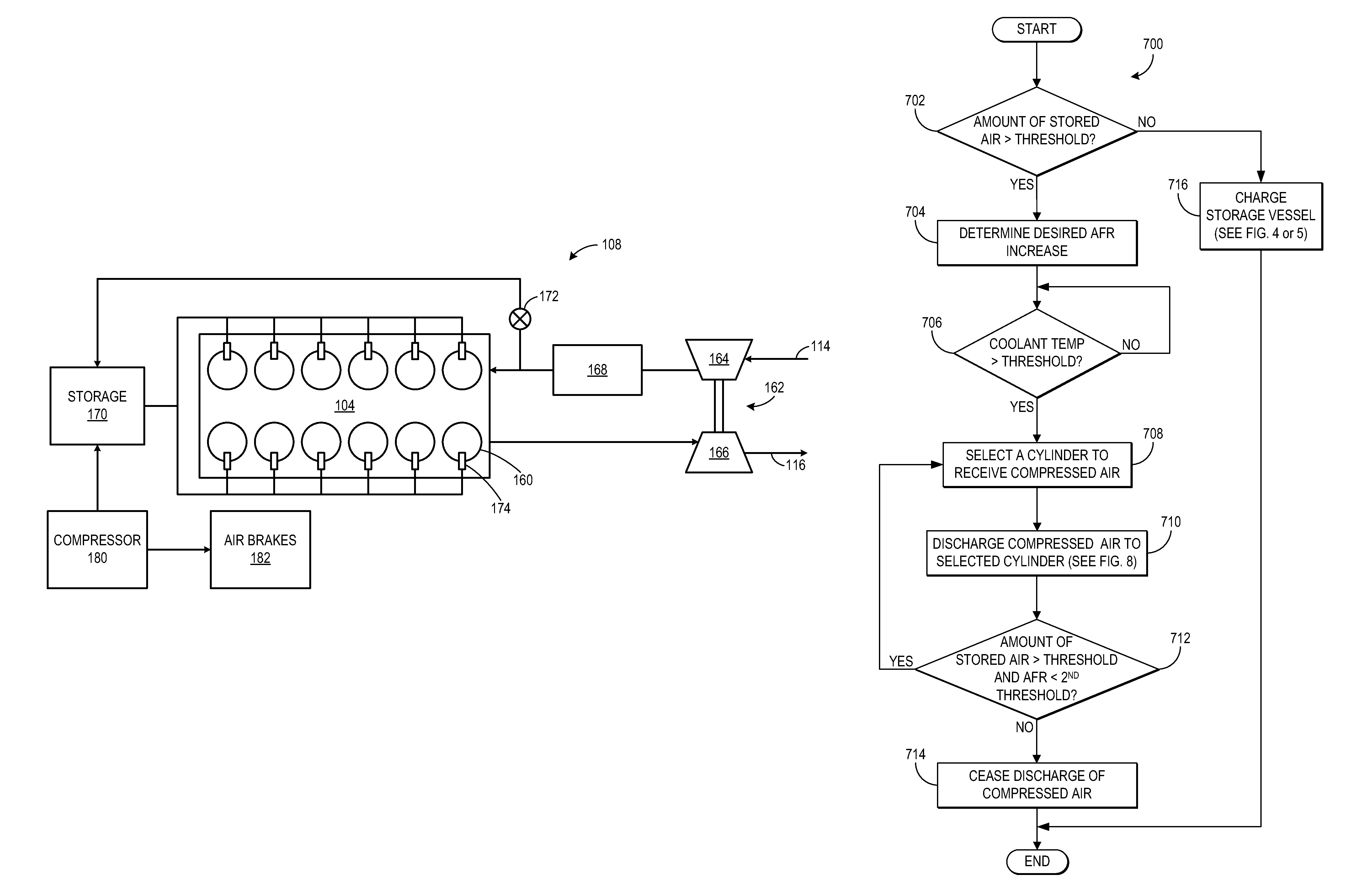
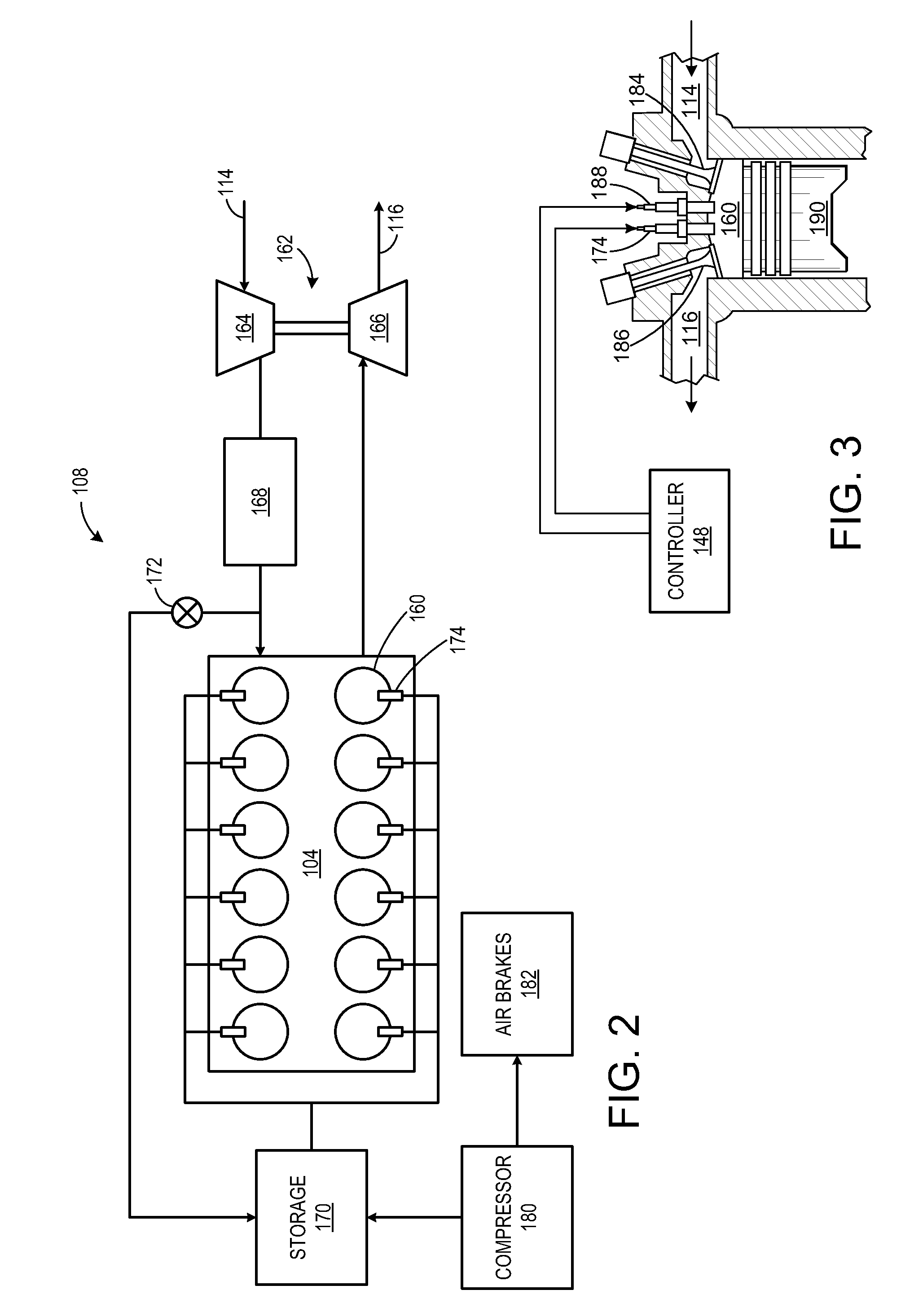
[0015]The following description relates to various method and systems for controlling transient engine response. In one example embodiment, a method for operating an internal combustion engine includes, under a first condition, charging a compressed air storage vessel via a compressor. The method further includes, under a second condition, directly injecting compressed air from the storage vessel to a cylinder of the engine to enhance fuel combustion. Under a third condition, the method includes ceasing the injection of compressed air from the storage vessel. In such a configuration, as will be described in detail below, the response of the engine during transient conditions may be improved. For example, because the compressed air is directly injected to the cylinder from the storage vessel, a time for the cylinder to receive the air is relatively short resulting in a fast engine response and less time in which an air-fuel ratio of the engine may decrease below a threshold air-fuel ...


PUM


Abstract

Various methods and systems for operating an internal combustion engine are provided. In one embodiment, an example method for operating an internal combustion engine includes, under a first condition, charging a compressed air storage vessel via a compressor. The method further includes, under a second condition, directly injecting compressed air from the storage vessel to a cylinder of the engine to enhance fuel combustion.

Description

FIELD[0001]Embodiments of the subject matter disclosed herein relate to controlling transient engine response in an internal combustion engine.BACKGROUND[0002]Many control approaches and schemes have been devised for internal combustion engines, particularly for large, relatively powerful diesel engines and engines running on other fuels. During periods of acceleration, a vehicle operator may command higher speed and / or torque from the vehicle, requiring higher output from the engine. In the case of rail vehicles and other transport vehicles, when steeper grades are encountered, additional torque or tractive effort is needed to maintain the speed of the vehicle, thereby increasing the power output demanded of the engine. As a result, during such a transient conditions, a greater amount of fuel may be injected to the engine; however, the fuel increase may not be immediately matched by a proportionate increase in air supplied to the engine. This may result in an air-fuel ratio that is...

Claims


Application Information

Patent Timeline
Patent Type & Authority Patents(United States)
IPC IPC(8): F02B33/44B60K6/00F02B23/00F02B41/00B60K8/00
CPCF02B37/10Y02T10/144F02B21/00F02B29/00Y02T10/12
Inventor GEYER, STEPHEN MARK
Owner GE GLOBAL SOURCING LLC
Why Eureka
Try Eureka