Trailing edge flap

a technology of railing edge and flap arrangement, which is applied in the direction of wing lift eficiency, air braking surface, wing adjustment, etc., can solve the problems of performance loss at the higher deflection required for landing, and achieve the effect of improving the lifting potential of the flap arrangement and beneficial low drag characteristics

Inactive Publication Date: 2013-10-29
AIRBUS OPERATIONS LTD
View PDF31 Cites 18 Cited by
  • Summary
  • Abstract
  • Description
  • Claims
  • Application Information

AI Technical Summary

Benefits of technology

[0008]The invention is advantageous in that the array of flap elements can be moved collectively, sealed together, to open up a single through slot between the main fixed portion of the aircraft wing and the array of flap elements. The flap arrangement can therefore be deployed like a standard single slotted flap with beneficial low drag characteristics. However, when the flap elements are deployed to open up a slot between adjacent flap elements, the lifting potential of the flap arrangement can be significantly improved without much of the complexity typically associated with multi-slotted flap arrangements.

Problems solved by technology

These are beneficial for take-off but suffer performance losses at the higher deflections required for landing.
Accordingly, it can be necessary for aircraft manufacturers to adopt a completely different flap arrangement for use on higher weight aircraft variants within a family, which is undesirable.

Method used


Image

  • Trailing edge flap
  • Trailing edge flap
  • Trailing edge flap

Examples


Embodiment Construction

)

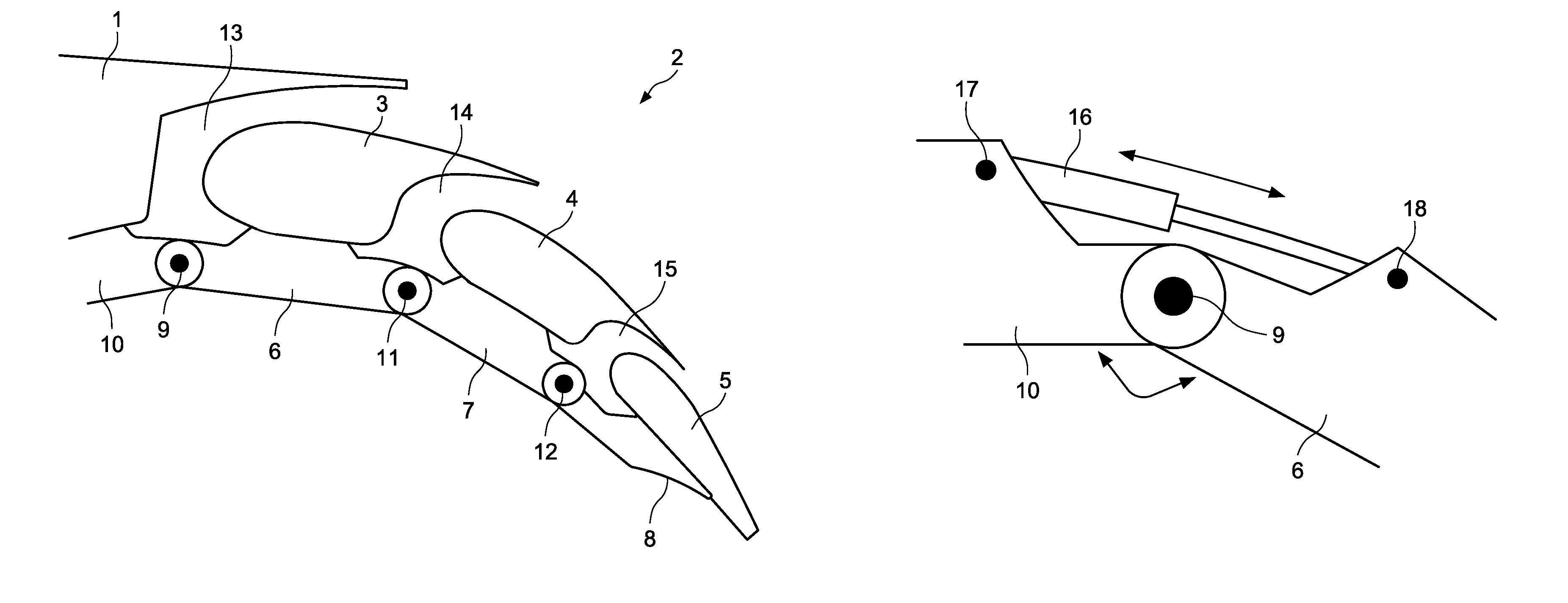
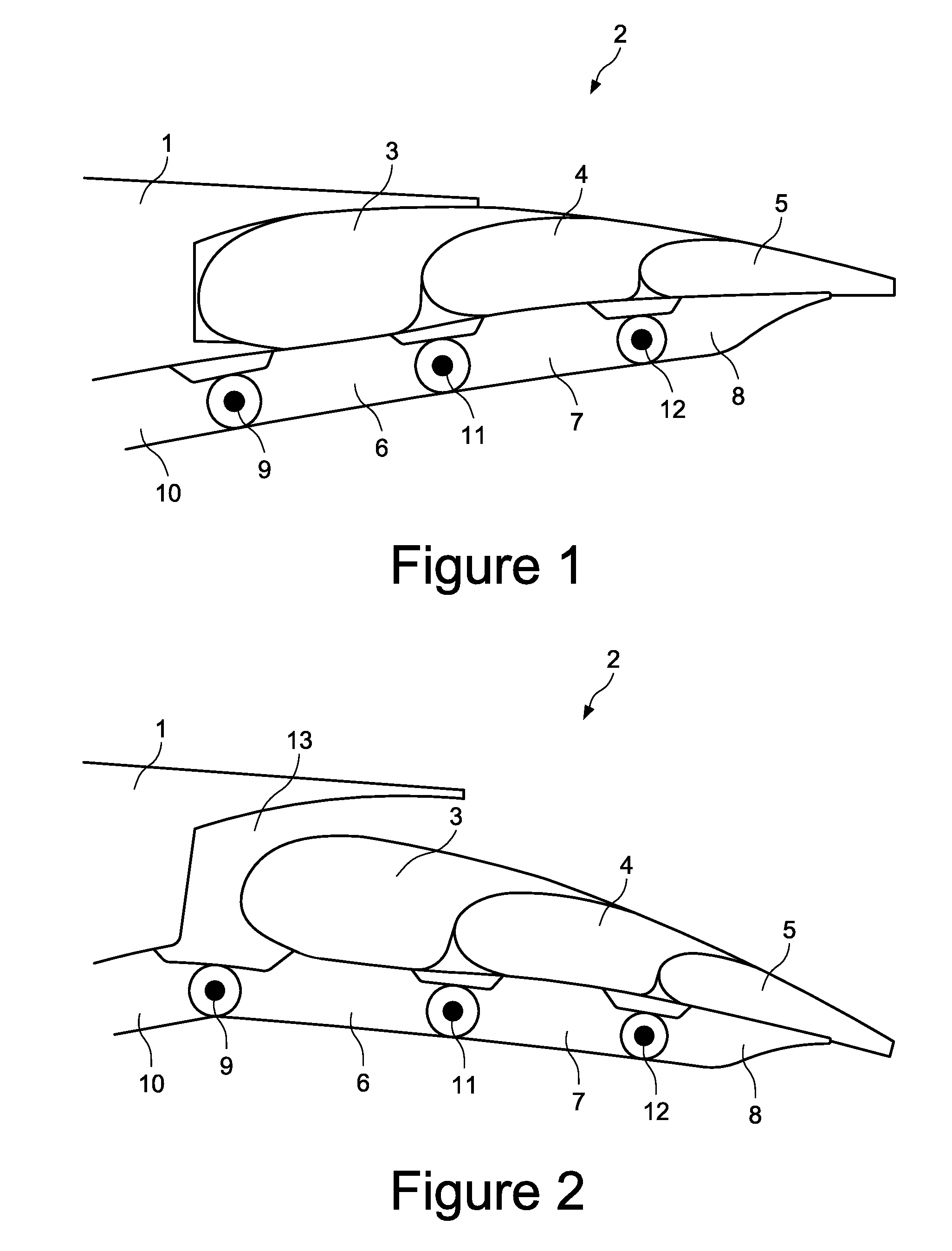
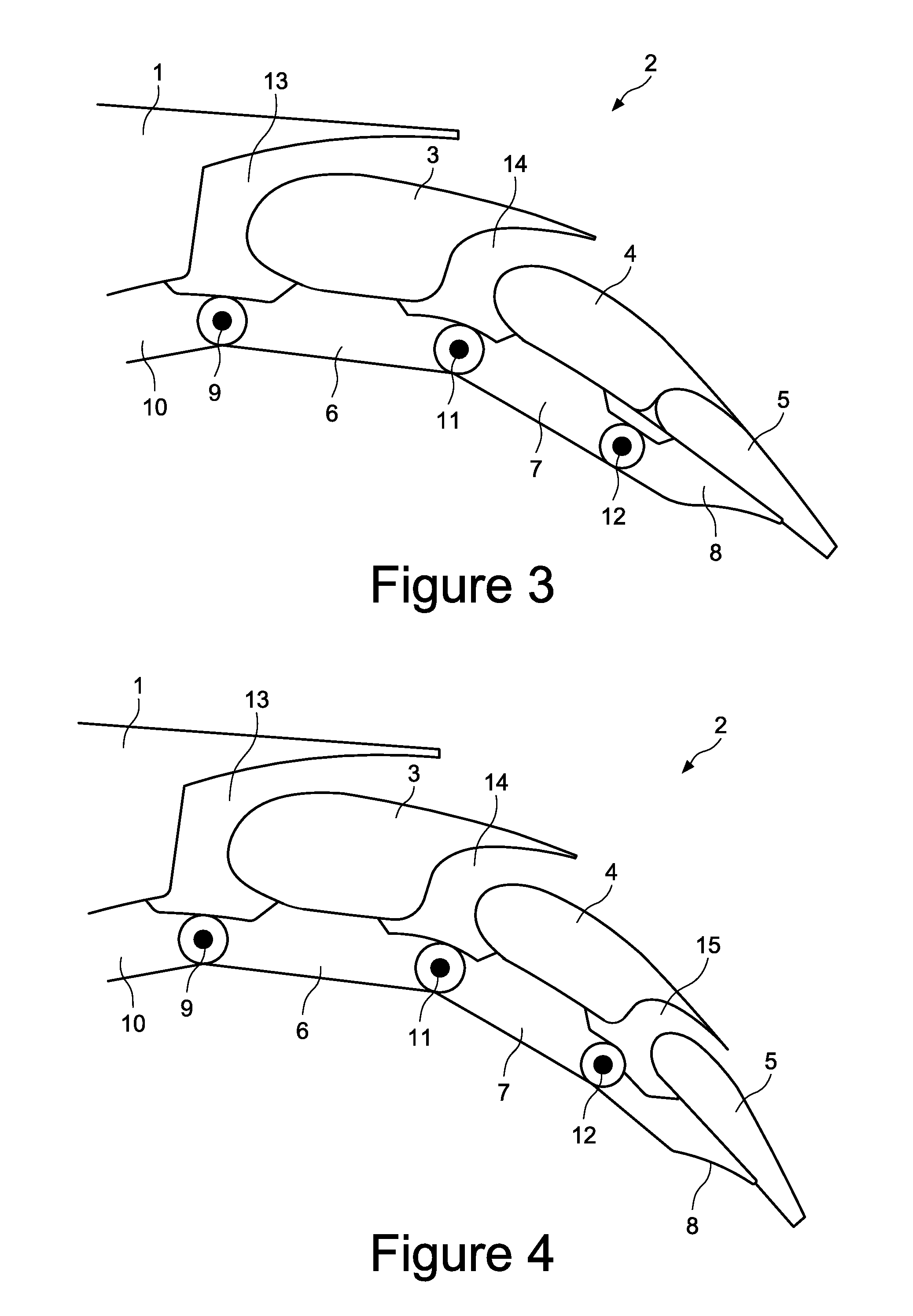
[0024]FIG. 1 shows an aircraft wing including a main fixed wing portion 1 and a trailing edge flap arrangement 2. The flap arrangement 2 includes an array of flap elements comprising a leading flap element 3, an intermediate flap element 4 and a trailing flap element 5.

[0025]Each flap element 3, 4, 5 is supported by a respective flap support 6, 7, 8. The flap elements are fixedly mounted on their respective flap supports. The leading flap support 6 is pivotally connected about a leading hinge point 9 to a fixed strut 10. The fixed strut is mounted on the fixed wing portion 1. The intermediate flap support 7 is pivotally connected about an intermediate hinge point 11 to the leading flap support 6. The trailing flap support 8 is pivotally connected about a trailing hinge point 12 to the intermediate flap support 7. The hinge points 9, 11, 12 are located forward and below their respective flap elements 3, 4, 5.

[0026]FIG. 1 shows the flap arrangement 2 in its retracted position. The ar...


PUM


Abstract

A trailing edge flap arrangement for an aircraft wing, comprising an array of flap elements each discretely moveable between a retracted and an extended position by a respective actuator, wherein the flap elements are arranged to be deployed so as to open up a through slot between an adjacent pair of the flap elements only when the aerodynamic leading element of the pair has reached its extended position. Also, a method of operating the trailing edge flap arrangement.

Description

RELATED APPLICATIONS[0001]The present application is based on, and claims priority from, Great Britain Application Number 0921007.1, filed Nov. 30, 2009, the disclosure of which is hereby incorporated by reference herein in its entirety.FIELD OF THE INVENTION[0002]The present invention relates to a trailing edge flap arrangement for an aircraft wing. The invention also relates to a method of operating a trailing edge flap arrangement.BACKGROUND OF THE INVENTION[0003]Aircraft wing trailing edge flaps are high lift devices which are typically deployed on take-off and landing to increase the lift coefficient by increasing the camber of the wing aerofoil. This can be achieved by rotating the flap downwardly about its hinge line with respect to the fixed wing portion. Some flaps, for example the Fowler flap, further increase the lift generated by the wing by also increasing the planform area of the wing. This is achieved by moving the flap along a track such that the flap moves aft and r...

Claims


Application Information

Patent Timeline
Patent Type & Authority Patents(United States)
IPC IPC(8): B64C9/20
CPCB64C9/26Y02T50/32Y02T50/30
Inventor MORRIS, STUART
Owner AIRBUS OPERATIONS LTD
Why Eureka
Try Eureka