Coated article with low-E coating including IR reflecting layer(s) and corresponding method

a technology of ir reflecting layer and coating, applied in the direction of vacuum evaporation coating, natural mineral layered products, transportation and packaging, etc., can solve the problems of one or more of the above-mentioned desirable characteristics to significantly deteriorate in an undesirable manner, and the coating to break down, and achieve low sheet resistance characteristics and high visible transmission.

Inactive Publication Date: 2008-03-18
GUARDIAN EURO S A R L +1
View PDF46 Cites 33 Cited by
  • Summary
  • Abstract
  • Description
  • Claims
  • Application Information

AI Technical Summary

Benefits of technology

[0011]In certain example embodiments of this invention, coated articles have been provided which are capable of realizing high visible transmission and / or low sheet resistance characteristics.

Problems solved by technology

However, heat treatment of coated articles typically requires use of temperature(s) of at least 580 degrees C., more preferably of at least about 600 degrees C. and still more preferably of at least 620 degrees C. The use of such high temperatures (e.g., for 5-10 minutes or more) often causes coatings to break down and / or causes one or more of the aforesaid desirable characteristics to significantly deteriorate in an undesirable manner.

Method used


Image

  • Coated article with low-E coating including IR reflecting layer(s) and corresponding method
  • Coated article with low-E coating including IR reflecting layer(s) and corresponding method

Examples


example

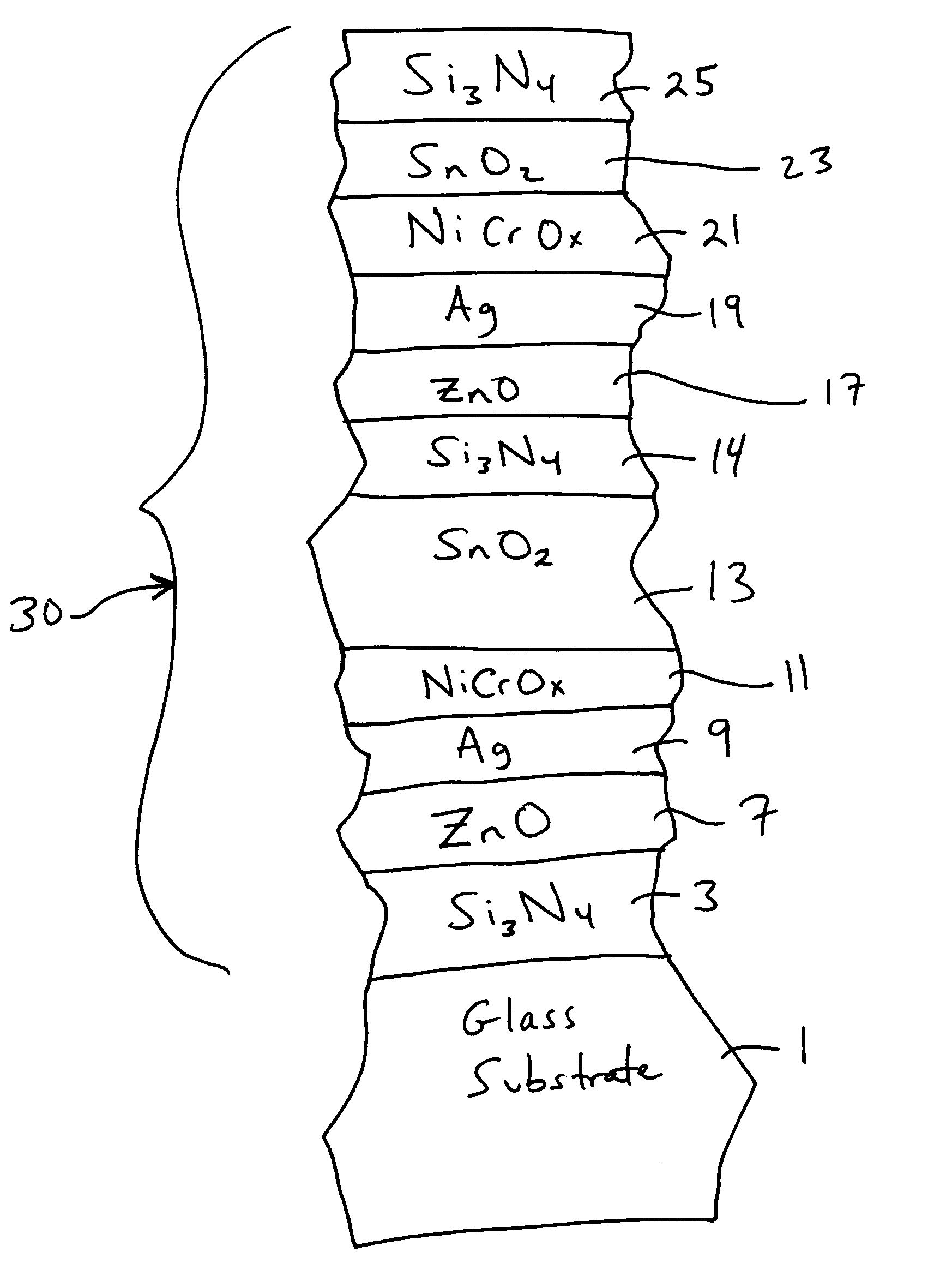
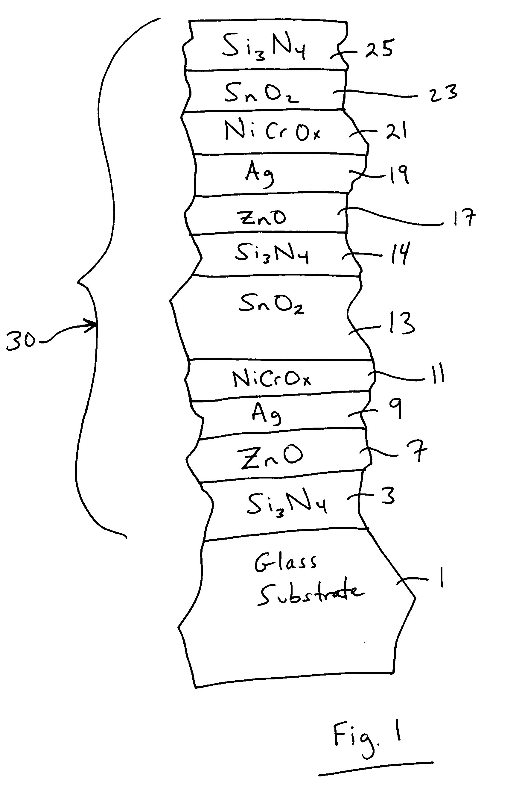
[0044]The following Examples were made via sputtering on 2.1 mm thick clear glass substrates so as to have approximately the layer stack set forth below and shown in FIG. 1. The thicknesses are approximations, and are in units of angstroms (Å).

[0045]

Layer Stack for Examples 1-2LayerExample 1Example 2Glass SubstrateSixNy177190ZnAlOx109109Ag9695NiCrOx2525SnO2535530SixNy126126ZnAlOx115115Ag9591NiCrOx2525SnO2127262Si3N4237109

[0046]It can be seen from the above that Examples 1 and 2 differed from one another primary with respect to the upper dielectric layers. In particular, about 40-60% (more precisely about 50%) of the top silicon nitride layer was replaced by tin oxide in Example 2 compared to Example 1. In other words, Example 2 used a thicker tin oxide layer 23 and thinner silicon nitride layer 25, compared to Example 1. Surprisingly, this permitted Example 2 to perform better with regard to mottling.

[0047]The processes used in forming the coated article of the Examples are set fort...


PUM

PropertyMeasurementUnit
hazeaaaaaaaaaa
sheet resistanceaaaaaaaaaa

Abstract

A coated article is provided that may be heat treated in certain example embodiments. A coating of the coated article includes zinc oxide inclusive layer(s) located under infrared (IR) reflecting layer(s) of a material such as silver. In certain example embodiments, coated articles are designed so as to realize higher visible transmission and/or lower sheet resistance values.

Description

[0001]This application is a continuation-in-part (CIP) of U.S. Ser. No. 10 / 787,823, filed Feb. 27, 2004; and is also a CIP of U.S. Ser. No. 10 / 453,790, filed Jun. 4, 2003, which is a divisional of each of (a) Ser. No. 09 / 794,224, filed Feb. 28, 2001 (U.S. Pat. No. 6,576,349); (b) Ser. No. 10 / 337,383, filed Jan. 7, 2003; now U.S. Pat. No. 6,723,211 and (c) Ser. No. 10 / 337,384, filed Jan. 7, 2003 (U.S. Pat. No. 6,686,050), which claim priority on U.S. Provisional Patent Application No. 60 / 217,101, filed Jul. 10, 2000, the disclosures of which are all hereby incorporated herein by reference.[0002]This invention relates to a coated article including a low-E coating. In certain example embodiments, the coated article may be heat treated (e.g., thermally tempered, heat bent and / or heat strengthened). Coated articles according to certain example embodiments of this invention may be used in the context of vehicle windshields, insulating glass (IG) window units, other types of windows, or in...

Claims


Application Information

Patent Timeline
Patent Type & Authority Patents(United States)
IPC IPC(8): B32B17/06B32B17/10C03C17/00C03C17/36C23C14/00C23C14/06
CPCB32B17/10B32B17/10036B32B17/10174C03C17/36C03C17/3618C03C17/3626C03C17/3639C03C17/3644C03C17/3652C03C17/366C03C17/3681C03C17/3694C23C14/0015C23C14/0084C23C14/0652B32B17/10009Y10T428/12618C03C2217/78Y10T428/12611Y10T428/12854Y10T428/12576B32B2605/00
Inventor LINGLE, PHILIP J.DIETRICH, ANTONMULLER, JENS-PETER
Owner GUARDIAN EURO S A R L
Why Eureka
Try Eureka