Radial release device

a radial release and spool technology, applied in the direction of mechanical control devices, process and machine control, fastening means, etc., can solve the problems of high shock load on the unit which is to be released, the design of two-piece spools presents a geometry, and the device imparts high shock load, so as to reduce the potential of friction lock up, prevent the movement of the spool segment, and reduce the contact angle

Active Publication Date: 2013-10-29
MAXAR SPACE LLC
View PDF14 Cites 19 Cited by
  • Summary
  • Abstract
  • Description
  • Claims
  • Application Information

AI Technical Summary

Benefits of technology

[0008]A release device having a multi-segment split spool with a central bore adapted to axially restrain a tensioned member. A tensioned tape is overlappingly wound around the spool segments thereby preventing radial movement of the spool segments. The overlapping winding allows for a low profile housing for the release device. Overlapping design of flat tape provides predictable unwinding dynamics upon release.
[0009]The multiple segments require less radial motion for release of the tensioned member. Further, multiple segments spool reduces the potential of “Friction lock up” due to smaller contact angle between each segment with the captured member (almost 90 for 4-segment, almost 60 for a 6-segment, and almost 45 for a 8-segment spool).

Problems solved by technology

Although useful in many applications, these devices imparted high shock loads into the units which they were to release, as well as the spacecraft itself.
A drawback of this design is that the wire, wrapped under tension around the outside of the spool, may have unpredictable dynamics in some cases when released.
In some cases, there may be risk of the wire fouling upon itself when released, which may prevent the spool from spreading far enough apart to allow the captured member to pass through, and thus this may prevent the release device from releasing the stowed spacecraft element.
Another drawback of this design is that a two piece spool design presents a geometry that requires significant radial movement of the spool pieces to affect the release.
Further, a two segment spool has geometric limitations as far as load carrying capacity and a phenomenon referred to as “Friction lock up” condition, a failure to release condition due to friction between the spool-to-captured member interface, and the fact that spherical (ball) end of the captured member leaves the segments contacting the two extreme points of each segment.
Further, multiple segments spool reduces the potential of “Friction lock up” due to smaller contact angle between each segment with the captured member (almost 90 for 4-segment, almost 60 for a 6-segment, and almost 45 for a 8-segment spool).

Method used


Image

  • Radial release device
  • Radial release device
  • Radial release device

Examples


Embodiment Construction

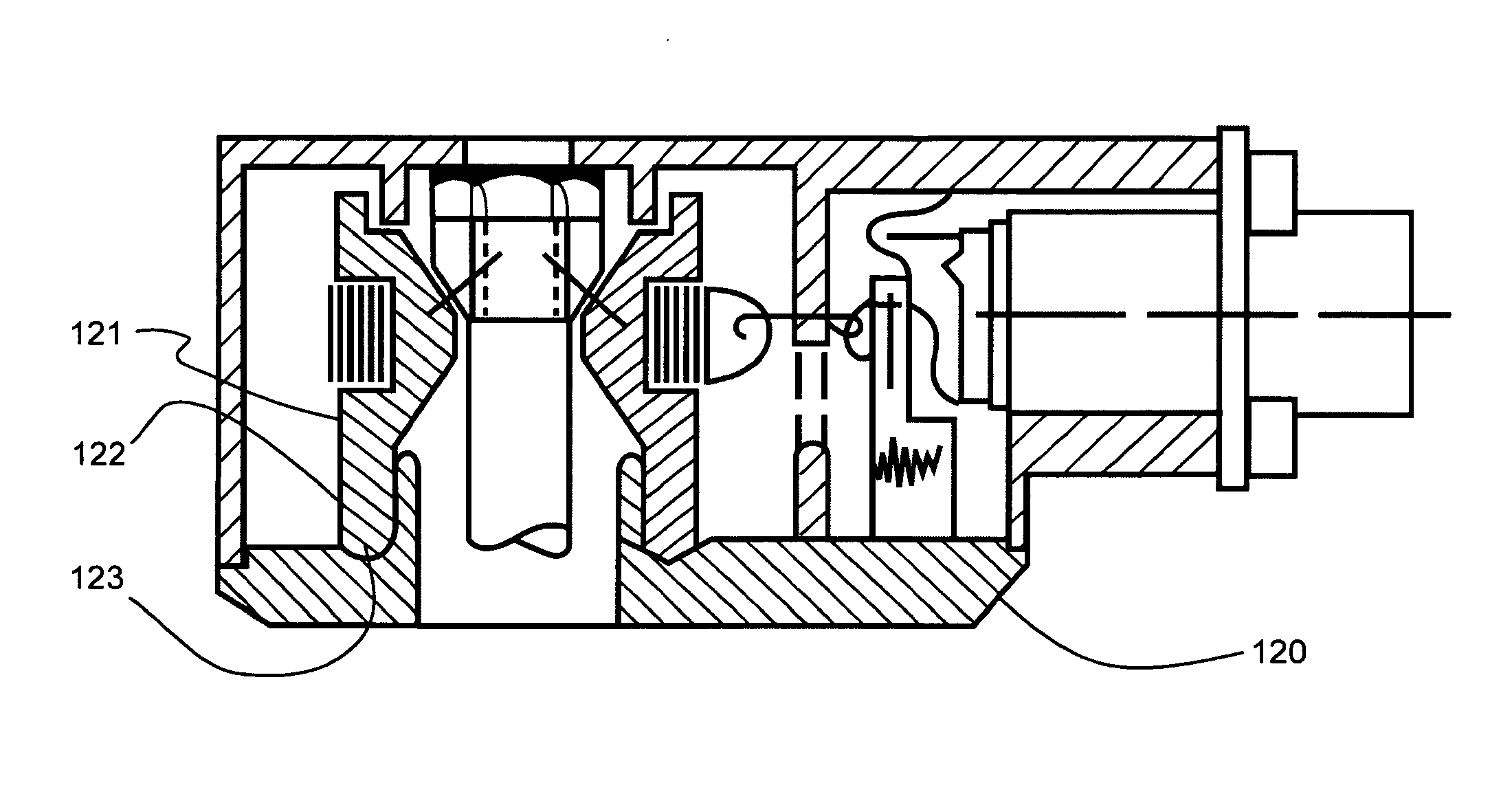
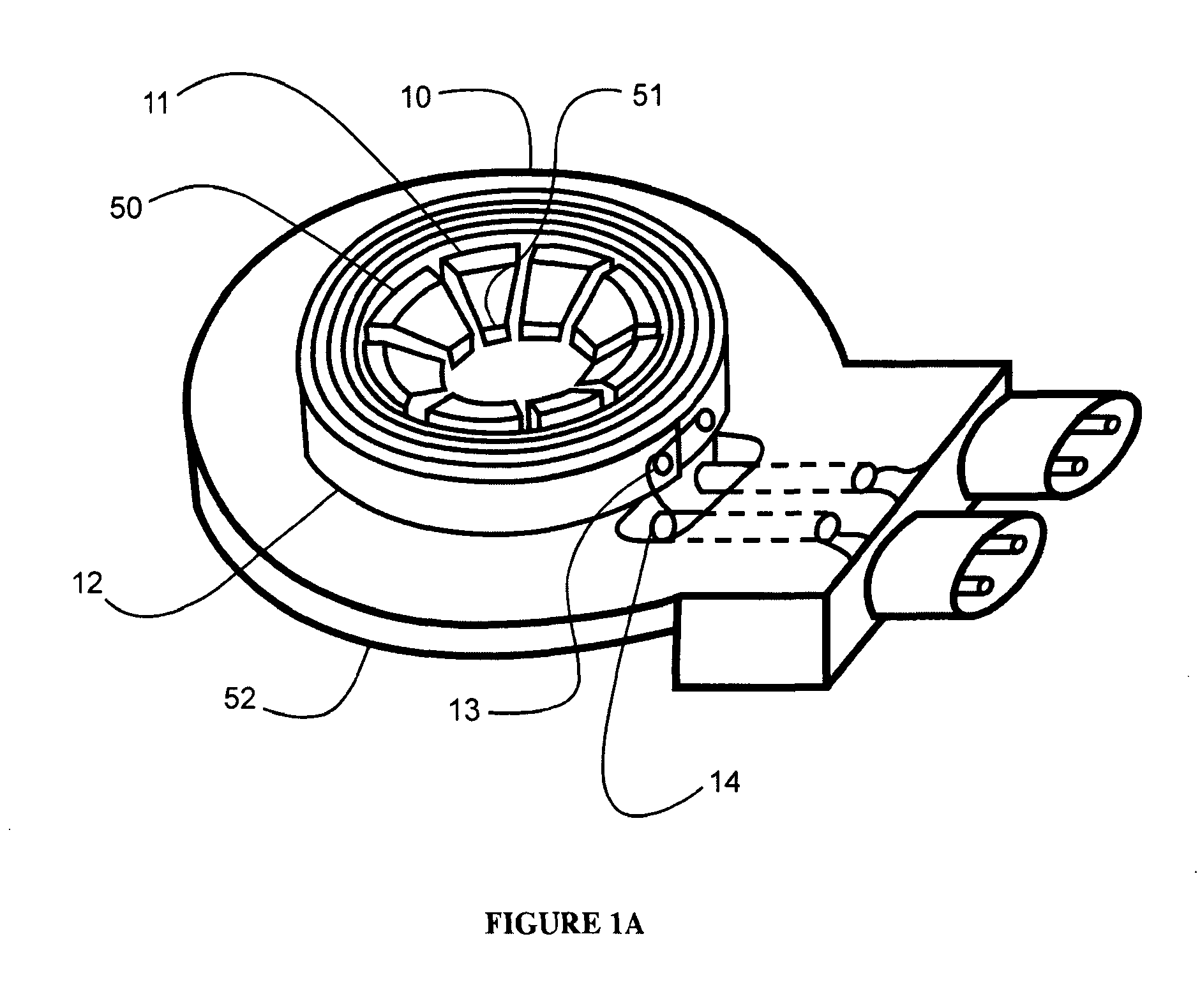
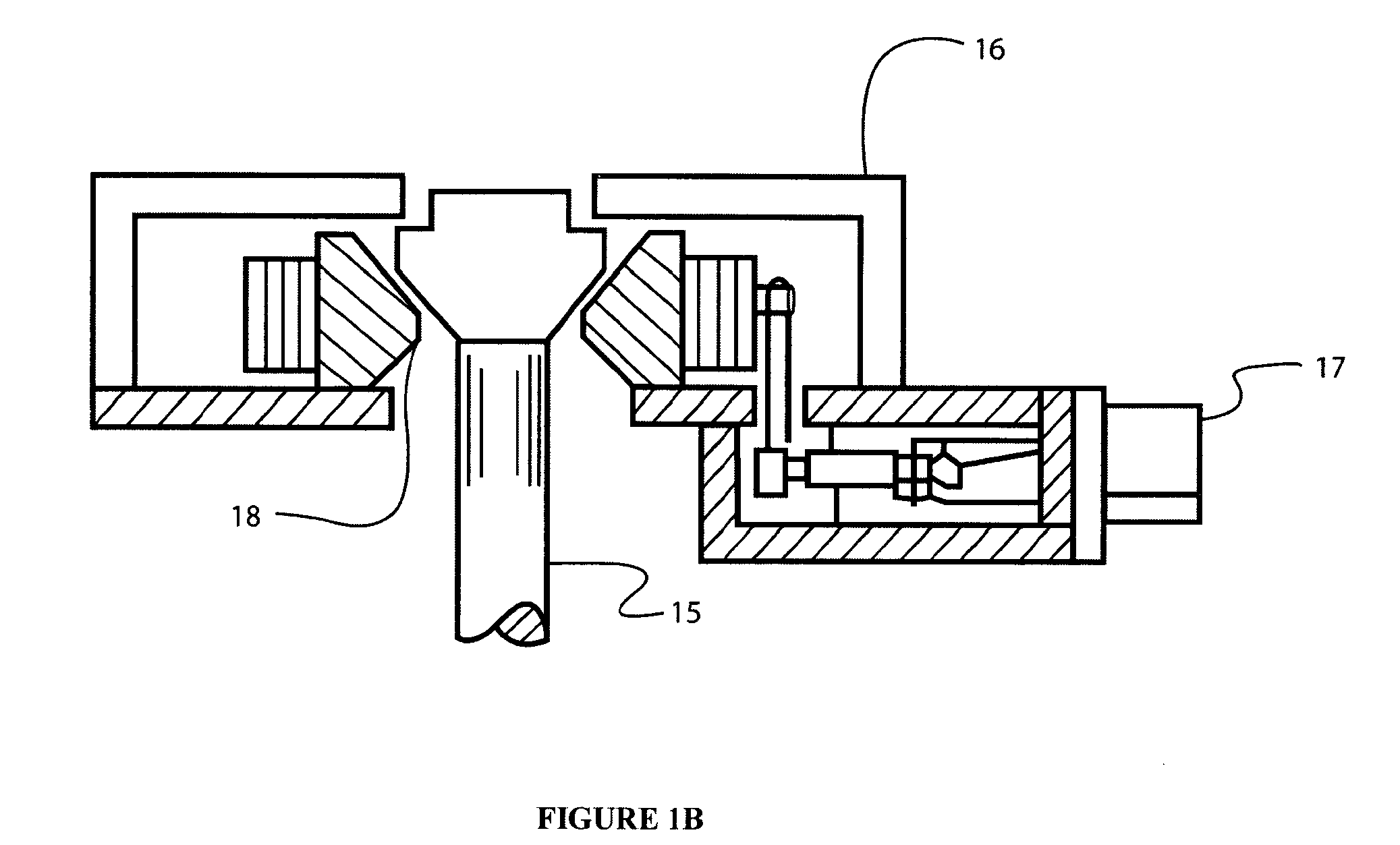
[0021]In some embodiments of the present invention, as seen in FIGS. 1A-B, a release apparatus 10 for controlling the deployment of a desired device by releasing a captured member 15 utilizes a multi-piece split spool 11 adapted to restrain the captured member 15. The multi-piece spool 11 consists of three or more segments 50 which define a central bore 51 adapted to restrain a captured member 15. In some embodiments, the spool 11 consists of six segments. In some embodiments, the spool consists of eight segments. As seen in cross-section in FIG. 1B, the segments of the spool are adapted to fittingly receive and axially restrain an expanded portion 18 of the captured member 15 when the segments 50 are constrained together as a unit. The internal area of the spool 11 in the interface area of the spool 11 with the expanded portion 18 of the captured member 15 may be conical in some embodiments. In some embodiments, the internal area of the spool 11 in this region may be a cone or a pa...


PUM


Abstract

A release device having a multi-segment split spool with a central bore adapted to axially restrain a tensioned member. A tensioned tape is overlappingly wound around the spool segments thereby preventing radial movement of the spool segments. The overlapping winding allows for a low profile housing for the release device. The multiple segments require less radial motion for release of the tensioned member.

Description

BACKGROUND[0001]1. Field of the Invention[0002]The present invention relates to a release device which may to release such items as antennas, solar arrays, positioning mechanisms, and other devices.[0003]2. Description of Related Art[0004]A release apparatus, such as a separation spool device, is used to release a captured member which constrains the deployment of a spacecraft element, such as a solar array and / or reflectors, in the stowed position. In many prior art devices, the spacecraft element was restrained with a wire or a holddown rod system which was released using a pyrotechnic device. Typically, the pyrotechnic device would fire a blade against a base, with the wire or rod to be cut and released. Although useful in many applications, these devices imparted high shock loads into the units which they were to release, as well as the spacecraft itself.[0005]A design that avoided the shocks associated with pyrotechnic release devices was the separation spool device, which used...

Claims


Application Information

Patent Timeline
Patent Type & Authority Patents(United States)
IPC IPC(8): G05G17/00
CPCB64G1/222B64G1/645B64G1/44B64G1/66F16B21/16Y10T74/11Y10T403/32114Y10T403/16Y10T403/443F16B2200/63
Inventor BAGHDASARIAN, VAROUJ G.
Owner MAXAR SPACE LLC
Why Eureka
Try Eureka