Micromechanical element

a micromechanical element and functional element technology, applied in the field of micromechanical elements, can solve the problems of non-linear deformation errors in large deflections, significant decrease of the optical quality of the focusing mirror, and deformation errors, so as to achieve positive effect on the resistance against mechanical interference effects, significant reduction of deviation from the ideal deformation profile, and reduction of deformation errors

Active Publication Date: 2013-10-29
FRAUNHOFER GESELLSCHAFT ZUR FOERDERUNG DER ANGEWANDTEN FORSCHUNG EV
View PDF25 Cites 9 Cited by
  • Summary
  • Abstract
  • Description
  • Claims
  • Application Information

AI Technical Summary

Benefits of technology

[0021]Embodiments are based on the central idea that deviations of the deformation profile of the main face of a micromechanical functional element can be reduced by integrating an inner frame or by partitioning the bendable main face into several parts. By using an inner frame, the deviations of the deformation profile of the main face from the ideal deformation profile resulting from the restoring forces of the holding elements can be significantly reduced. Thereby, for example, more rigid holding elements can be used, which can have a positive effect on the resistance against mechanical interference effects.
[0022]In the same way, by partitioning the plate-shaped micromechanical functional element, a deviation from the ideal deformation profile can be significantly reduced. In particular, thereby, the deviation from the ideal deformation profile can also be reduced at large deflections (strong curvature) of the main face of the plate-shaped micromechanical functional element, even when the bending is higher than the overall thickness of the plate-shaped micromechanical functional element. Thus, even thin plate-shaped micromechanical functional elements can be used, whereby power consumption or electric drive voltages for realizing the variable bending of the main face of the plate-shaped micromechanical functional element can be reduced. Additionally, manufacturing the micromechanical element is possible without extra effort, since etching open trenches for structuring the plate-shaped micromechanical functional element is necessitated anyway.

Problems solved by technology

This results in deformation errors by restoring forces of the suspension of the mirror plate 1110.
The amount of deviation from the ideal deformation profile depends on the lateral size of the mirror plate (e.g. diameter d in a circular plate), occurs already at small deflections and results in a significant decrease of the optical quality of the focusing mirror.
Additionally, non-linear deformation errors in large deflections can occur.
These fold-like deviations from the ideal deformation profile occur within the whole mirror plate and result in a significant decrease of the optical quality at large deflections (curvatures) of the focus mirror.
However, producing thick mirror plates with the help of microsystem technology is very expensive (reason: depositing and structuring of thick layers) and the bending moment to be overcome is non-linearly dependent on the plate thickness (bending moment˜plate thickness3), significantly higher driving forces in the form of higher actively coupled lateral expansions (which have to be generated by higher electric voltages, for example in the case of electroactive functional layers) are necessitated for bending thick plates.

Method used


Image

  • Micromechanical element
  • Micromechanical element
  • Micromechanical element

Examples


embodiment 700

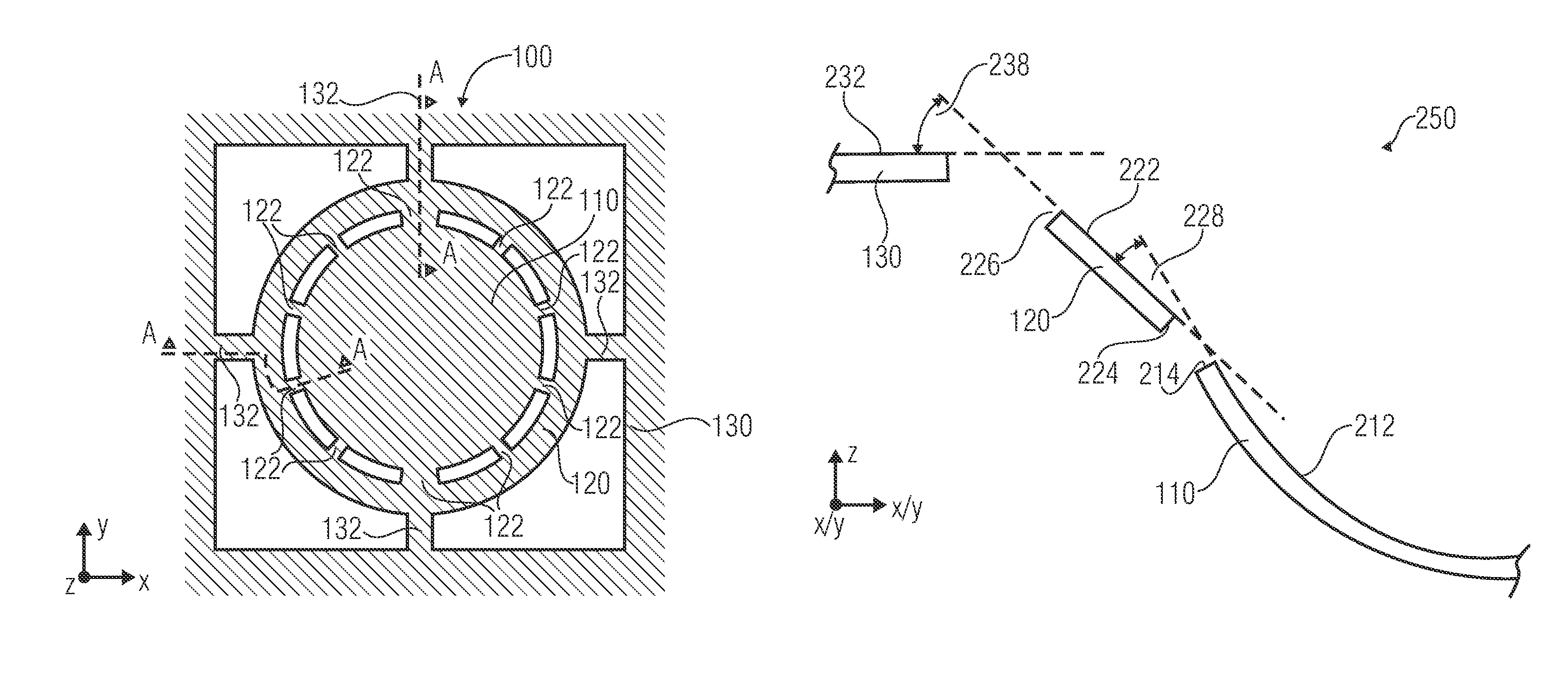
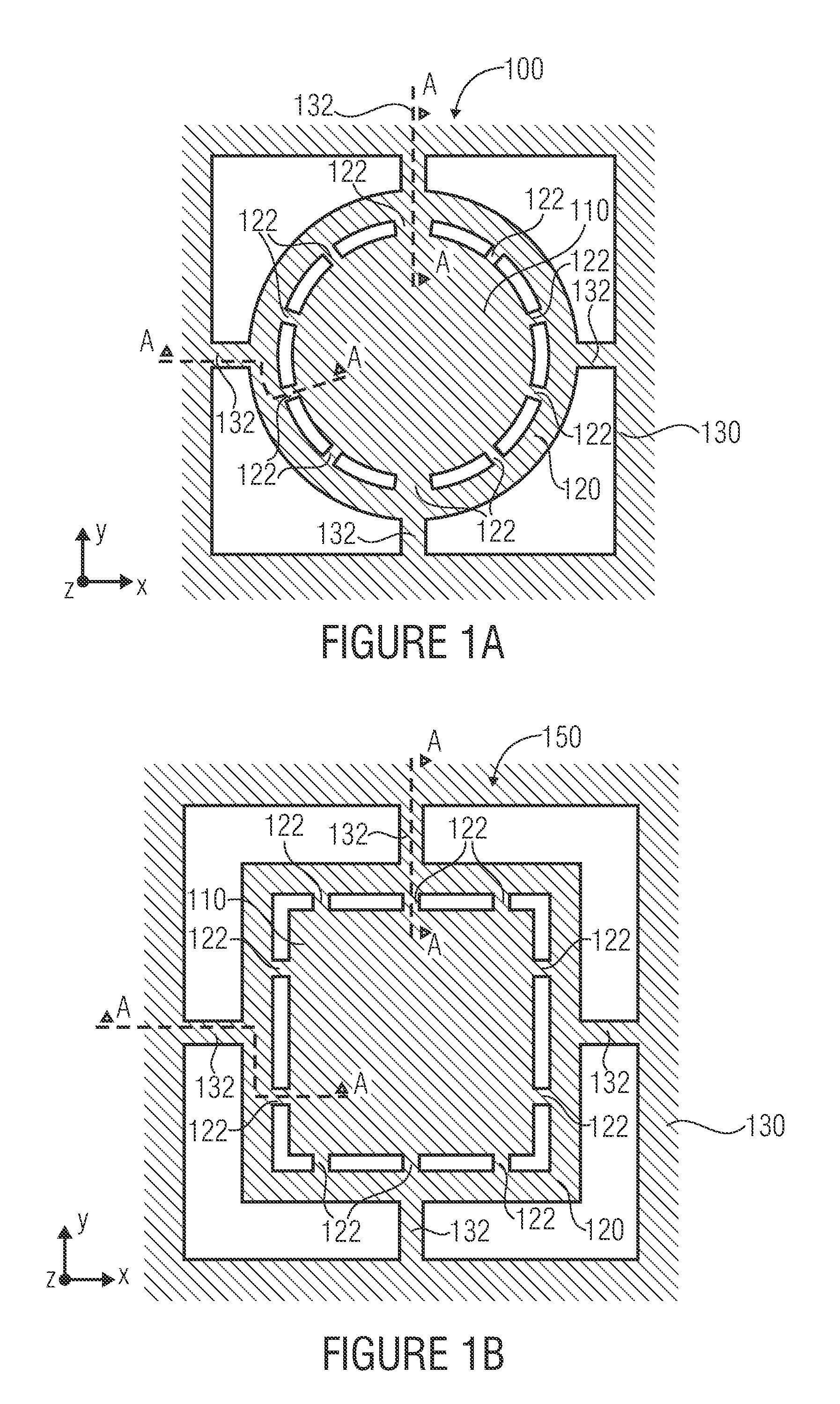
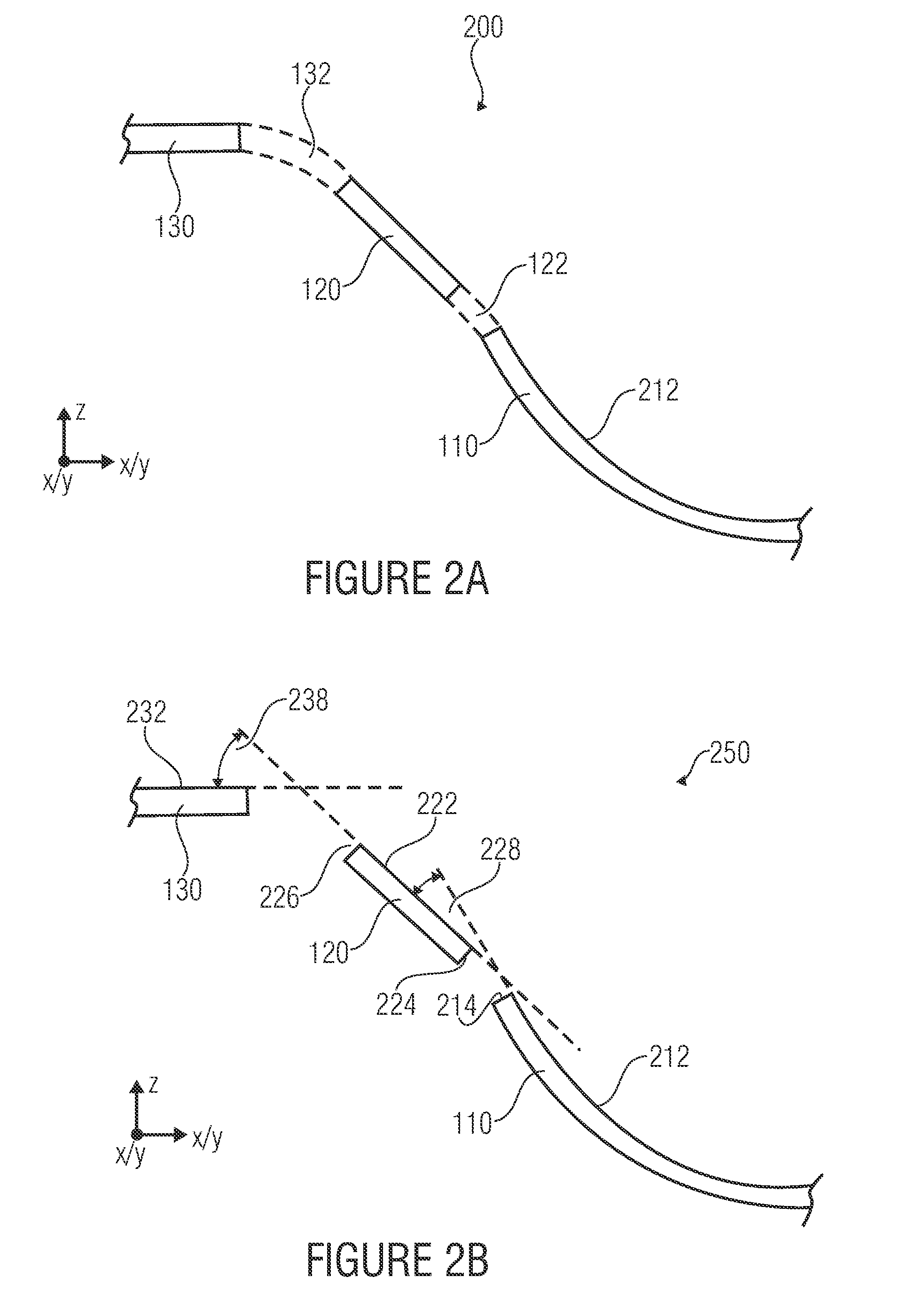
[0077]With the help of a described approach, the inventive embodiment 700 shown in FIG. 7 can successfully reduce the deviation from the ideal deformation profile resulting from the non-linear stress of the overall plate (plate-shaped micromechanical functional element). Separating the entire mirror plate into two partial plates 510, 520 has been realized by open trenches 722. Both partial plates are connected to one another by several connecting pieces 122. The number and position of these connecting pieces 122 can again be determined with the help of geometrical optimizations.

[0078]By the embodiment shown in FIG. 7, for example, a micromirror for active focus variation can be realized, with which a circular mirror plate is partitioned by a circular open trench 722 (with interruption by the connecting pieces 122) and two mirror plates 510 and 520 (first and second part of the plate-shaped micromechanical functional element).

embodiment 800

[0079]As already described above, a further reduction of the deviation of the surface profile can be enabled by partitioning into several mirror plates. This is shown exemplarily in the inventive embodiment 800 in FIG. 8. Here, the mirror plate has been partitioned into three partial plates 510, 520 and 830 with the help of open trenches 722. The sections of the mirror plate are again connected to one another by connecting pieces 122.

[0080]Theoretically, the optimum diameters of the partial plates should be as follows:

[0081]d1d=23⁢⁢andd2d=13

Since the partial plates are, however, non-ideally resiliently connected to one another via connecting pieces 110 and hence influence each other, the ratios d1 / d and d2 / d found by geometrical optimization deviate therefrom. The size of the partial plates and the amount and position of connecting pieces can again be found out by geometrical optimization.

[0082]The micromechanical element 800 enables also, for example, a realization of a micromirror...


PUM


Abstract

A micromechanical element includes a plate-shaped micromechanical functional element, an inner frame and an outer frame. Thereby, a curvature of a main face of the plate-shaped micromechanical functional element is variable. The inner frame encloses the plate-shaped micromechanical functional element along an edge of the main face and is connected to the plate-shaped micromechanical functional element via a plurality of connecting pieces. The outer frame is connected to the inner frame via at least two holding elements. The inner frame is connected to the plate-shaped micromechanical functional element and the outer frame, such that a first angle between the main face of the plate-shaped micromechanical functional element and a main face of the inner frame is smaller than a second angle between a main face of the outer frame and the main face of the inner frame, when the main face of the plate-shaped micromechanical functional element is in a bent state.

Description

CROSS-REFERENCE TO RELATED APPLICATIONS[0001]This application claims priority from German Patent Application No. 102010028111.5-54, which was filed on Apr. 22, 2010, and is incorporated herein in its entirety by reference.BACKGROUND OF THE INVENTION[0002]Embodiments according to the invention relate to a micromechanical element and a method for producing a micromechanical element.[0003]A series of different micromirrors are known. For example, micromechanically produced mirrors for active focus variation bendable in a convex and / or concave manner are known. A very simplified illustration (cross-section) of a mirror deflectable according to the bimorph principle is shown, for example, in FIGS. 9a and 9b. Here, the mirror plate 900 consists of at least two layers 910 and 920 of different materials.[0004]In order to be able to actively bend the mirror plate, a lateral mechanical expansion εx and εy has to be actively adjustable in at least one layer. The actively adjustable expansion c...

Claims


Application Information

Patent Timeline
Patent Type & Authority Patents(United States)
IPC IPC(8): G02B26/00
CPCB81B3/0048B81B2201/047B81B2203/0109B81B2203/0163G02B26/0833
Inventor CONRAD, HOLGERJUNG, DENIS
Owner FRAUNHOFER GESELLSCHAFT ZUR FOERDERUNG DER ANGEWANDTEN FORSCHUNG EV
Why Eureka
Try Eureka