
Modular visual and electronic identification tag

a module and electronic technology, applied in the field of identification tags, can solve the problems of disincentivization of the highly beneficial use of both visual and rfid tags in feed lot operations, and achieve the effect of facilitating the use of both visual and rfid tags

Inactive Publication Date: 2013-11-05
DATAMARS
View PDF6 Cites 8 Cited by
  • Summary
  • Abstract
  • Description
  • Claims
  • Application Information

AI Technical Summary

Benefits of technology

[0015]Another objective of providing some embodiments of the present invention is to facilitate the easy and non-destructive separation of visual and RFID tags removed from an animal, in cases when either or both such tags are desired to be used on another animal.
[0016]In satisfaction of these and related objectives, certain embodiments of Applicant's present invention provide a modular animal ear tag with both visual identification and RFID identification means. In preferred embodiments, the visual and RFID identification means are easily mated and subsequently separated to facilitate re-use of either or both such components. In addition, use of the combined visual and RFID tag afforded by the present invention is more humane, as it involves, rather than multiple punctures for each type of tag, a single operation that is identical to placement of an RFID tag alone.

Problems solved by technology

Feed lot operations, however, do not require strict, single-use of tags, as identification and tracking of animals in that context is usually, merely local management issue.
At present, the would-be highly beneficial use of both visual and RFID tags in feed lot operations is disincentivized, if not cost-prohibitive in some cases, in part, because there is no present, practical avenue for re-using RFID tags, especially in conjunction with using visual tags.

Method used


Image

  • Modular visual and electronic identification tag
  • Modular visual and electronic identification tag
  • Modular visual and electronic identification tag

Examples


Embodiment Construction

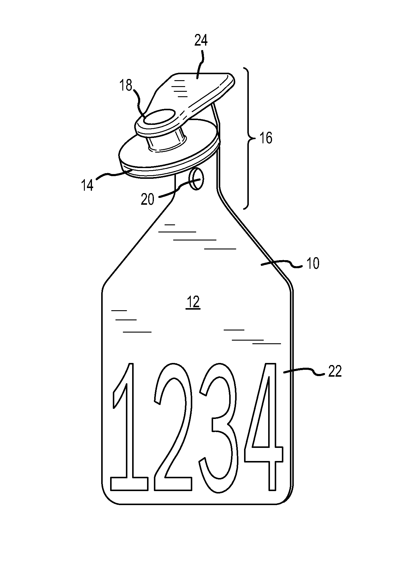
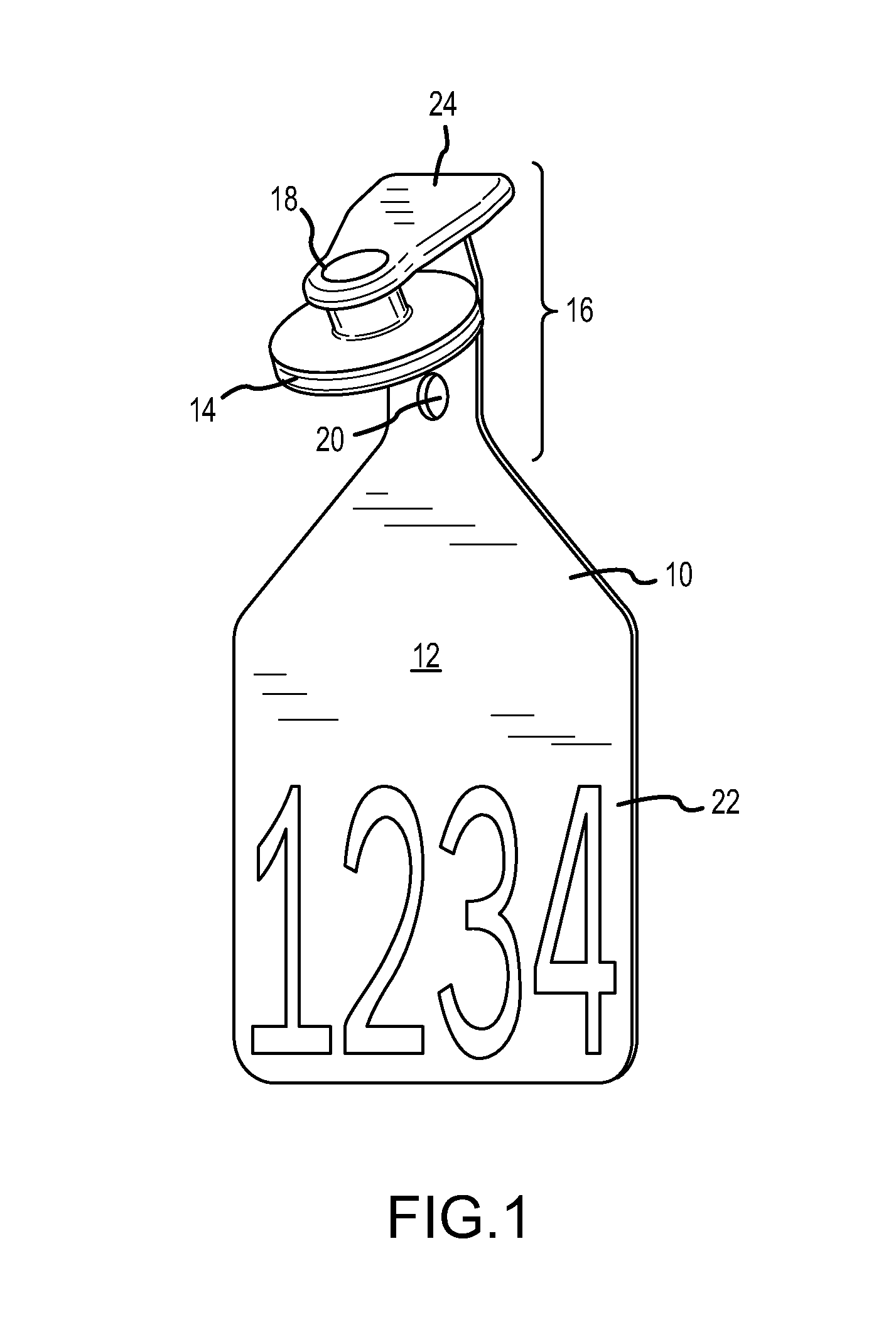
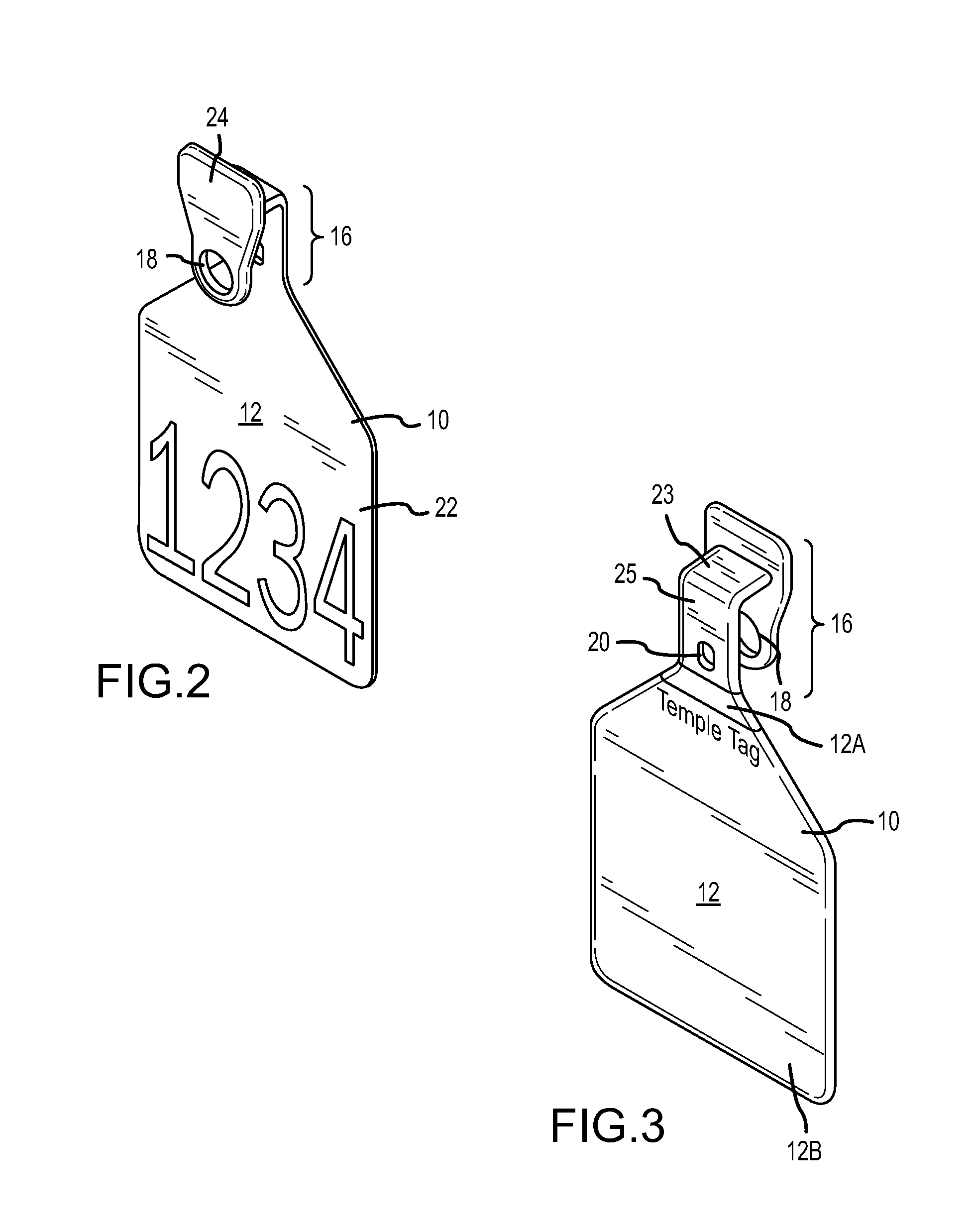
[0022]The assemblage of one preferred embodiment of the present invention is depicted in the accompanying FIGS. 1-3. At its most basic level, such an embodiment will include a visual ear tag that includes facilities for reversible mating between the visual ear tag and an RFID tag. The combined assemblage is easily attached to, and subsequently removed from an animal through use of conventional car tag attachment tools that are well known in the art.

[0023]Referring again to FIGS. 1-3, the modular animal ear tag of the present invention is identified generally by the reference number 10. Tag 10 includes a visual ear tag panel 12, with a top end 12A and a bottom end 12B, on which will typically be imprinted indicia 22 that reflects a unique identifier that is assigned to the particular recipient animal and maintained in an operators records.

[0024]An extension 16 from one end of panel 12 includes holes 18 and 20 formed there through. Extension 16 also has a front plate 24 and a back pla...


PUM


Abstract

A modular animal ear tag with both visual identification and RFID identification components, with the visual and RFID identification components being easily mated and subsequently separated to facilitate re-use of either or both such components.

Description

BACKGROUND OF THE INVENTION[0001]1. Field of the Invention[0002]Applicant's invention relates identification tags, and particularly to both visual and electronically readable identification tags used to identify and manage livestock.[0003]2. Background Information[0004]The United States Beef Industry annually markets tens of millions of animals to supply both domestic and foreign demand for safe, high quality beef. These animals are fed in thousands of confinement feeding operations (“feed lots”) scattered across the country. While many of these operations are small (less than 4000 head) a vast majority (over 75%) of cattle sold pass through these commercial operations.[0005]These larger facilities are characterized by multiple owners of the cattle throughout the feed lot(s), which mixture creates a need for identification of cattle, or groups of cattle, in a quick and easily distinguished manner. First the plastic (visual) ear-tag industry arose to meet such needs, and this was fol...

Claims


Application Information

Patent Timeline
Patent Type & Authority Patents(United States)
IPC IPC(8): G06K19/06
CPCA01K11/004
Inventor MCCOY, WILLIAM E.
Owner DATAMARS
Learn More