
Image reconstruction method and X-ray CT apparatus

a reconstruction method and a technology of computed tomography, applied in tomography, instruments, nuclear engineering, etc., can solve the problem that another projection data cannot be used without waste, and achieve the effect of improving image quality

Active Publication Date: 2013-11-05
GE MEDICAL SYST GLOBAL TECH CO LLC
View PDF26 Cites 2 Cited by
  • Summary
  • Abstract
  • Description
  • Claims
  • Application Information

AI Technical Summary

Benefits of technology

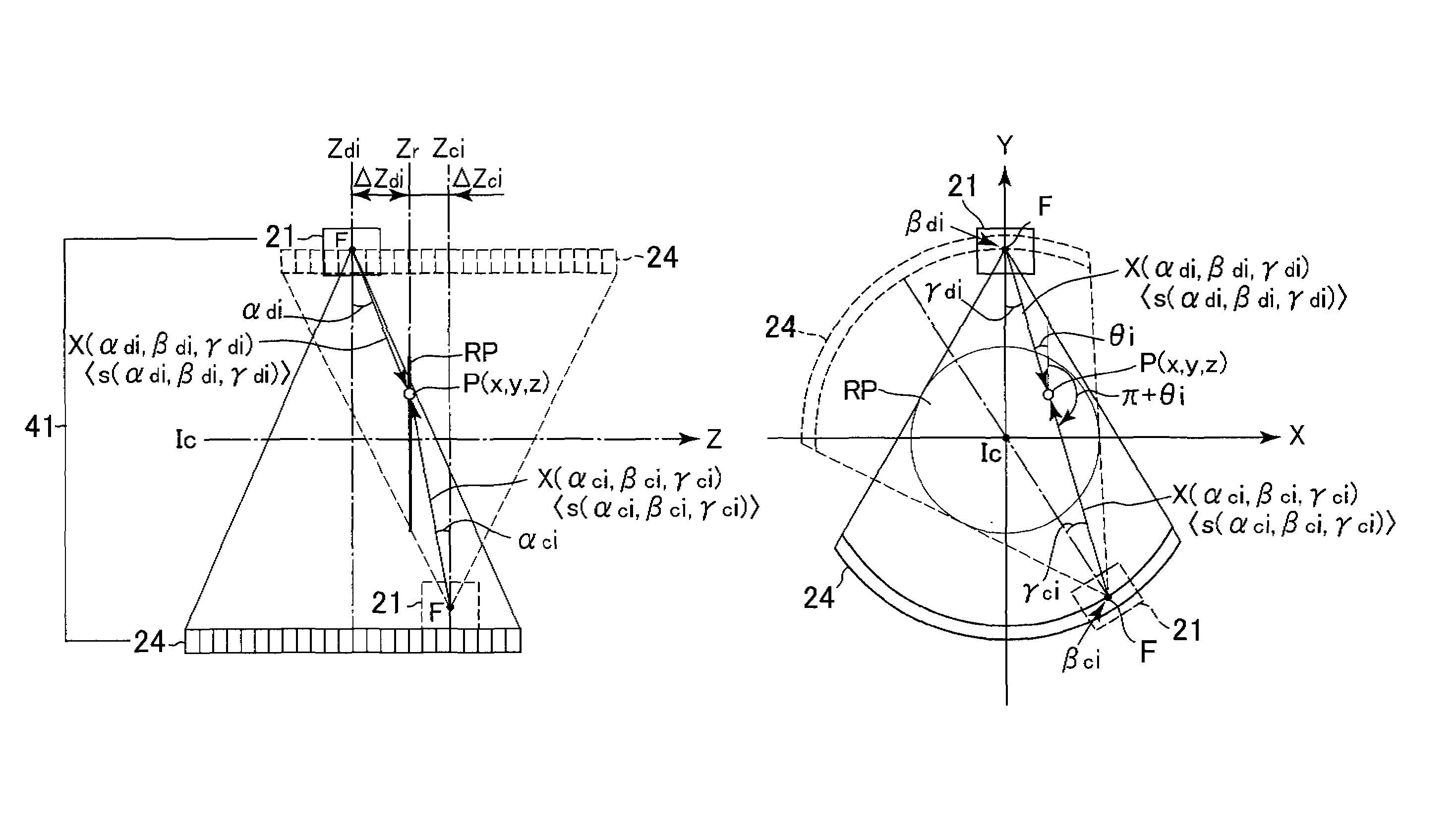
The patent proposes a method to improve the image quality of a computed tomography (CT) image by using multiple X-ray beams to reconstruct the pixel data. The method prevents distortion of the X-ray beams caused by small distances between the X-ray generator and the detector system. This is achieved by performing a backprojection arithmetic operation with weighting based on a distance between the X-ray beam and the reconstruction plane of the CT image. This method ensures reliable utilization of projection data based on X-ray beams close to the reconstruction plane, even if the distance between the X-ray beam and the reconstruction plane is small. Overall, this method improves the image quality of CT images and enhances the accuracy of the diagnostic information obtained from them.

Problems solved by technology

Namely, although the two are both useful projection data, only one projection data substantially contributes to the reconstruction, and another projection data cannot be utilized without wastes.

Method used


Image

  • Image reconstruction method and X-ray CT apparatus
  • Image reconstruction method and X-ray CT apparatus
  • Image reconstruction method and X-ray CT apparatus

Examples


Embodiment Construction

[0055]Embodiments of the present invention will hereinafter be described in further detail in accordance with an embodiment illustrated in the accompanying drawings. Incidentally, the present invention is not limited to or by the embodiments described herein.

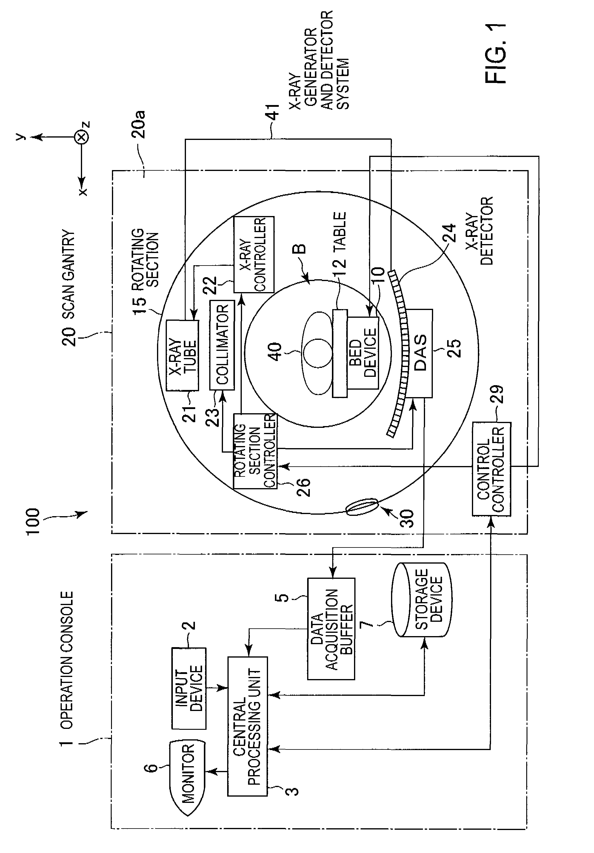
[0056]FIG. 1 is a configuration diagram showing an X-ray CT apparatus 100 according to the present embodiment.

[0057]The X-ray CT apparatus 100 is equipped with an operation console 1, a bed device 10, and a scan gantry 20.

[0058]The operation console 1 is equipped with an input device 2 which accepts an input from a user, a central processing unit 3 which executes control for data acquisition, processing of acquired data, etc., a data acquisition buffer 5 which acquires projection data acquired by the scan gantry 20, a monitor 6 which displays each reconstructed CT image, based on the projection data, and a storage device 7 which stores programs, image data about CT images, etc. therein.

[0059]The bed device 10 is equipped with a ...


PUM


Abstract

An image reconstruction method includes a reconstruction algorithm of pixel data, weighting coefficients by which first projection data and second projection data at which a corresponding X-ray beam passes through a pixel lying on a reconstruction plane and which are opposite in view angle direction to each other, are to be multiplied, are calculated by equations each using a term of a distance between an X-ray generator and detector system and the reconstruction plane plus an offset distance at the acquisition of the projection data.

Description

CROSS REFERENCE TO RELATED APPLICATIONS[0001]This application claims the benefit of Japanese Patent Application No. 2009-000140 filed Jan. 5, 2009, which is hereby incorporated by reference in its entirety.BACKGROUND OF THE INVENTION[0002]The embodiments described herein relate to an image reconstruction method and an X-ray CT (Computed Tomography) apparatus.[0003]When a CT image is reconstructed based on projection data acquired by an X-ray CT scan, pixel data of each pixel on a reconstruction plane, corresponding to the CT image has heretofore been reconstructed using general formulas for backprojection arithmetic operation including weighting, such as expressed in the following equations (refer to, for example, “A three-dimensional weighted cone beam filtered backprojection (CB-FBP) algorithm for image reconstruction in volumetric CT under a circular source trajectory”, Physics In Medicine And Biology, 50 (2005), P.3889-3905, Xiangyang Tang, Jiang Hsieh, Akira Hagiwara, et al.).[...

Claims


Application Information

Patent Timeline
Patent Type & Authority Patents(United States)
IPC IPC(8): A61B6/03
CPCG06T11/006G06T2211/421A61B6/027
Inventor HAGIWARA, AKIRA
Owner GE MEDICAL SYST GLOBAL TECH CO LLC
Learn More