High volume sampling front end collection device

a collection device and high-volume technology, applied in the field of high-volume sampling front-end collection devices, can solve the problems of affecting the movement of operators, requiring a large footprint in which to operate, and taking too much time to prepare liquid samples, etc., to achieve the effect of facilitating secondary filter transport, reducing costs, and reducing weight and size relative to state-of-the-art sampling systems

Active Publication Date: 2013-11-12
US DEPT OF HOMELAND SECURITY
View PDF11 Cites 14 Cited by
  • Summary
  • Abstract
  • Description
  • Claims
  • Application Information

AI Technical Summary

Benefits of technology

[0023]An object of the invention is to provide efficient and rapid collection of compounds from the surfaces of sea cargo containers, pelletized cargo, and much smaller surfaces such as shoe soles. A feature of the invention is that it is a portable device which can collect particles and vapors simultaneously on the same sample sequestration carrier. Another feature of an embodiment of the invention is that the portable device provides sample extraction and retention of target moieties for immediate analysis or delayed analysis. An advantage of the invention is that it will hold the trapped vapor compounds from an hour to a few days; the timeframe for retention of sample within the invention is dependent upon the choice of resin used within the sample sequestration carrier and chemical composition of the sample collected. An advantage of the invention is that the sample sequestration carrier is interchangeable so as to allow further sampling with the same device using unloaded carriers.
[0024]Another object of the invention is providing a portable explosive detection screening device, its portability defined as being transportable within a shirt pocket of a user. A feature of the invention is it is adapted for use with conventional vacuum systems, and analytical systems. Another feature of the invention is that the sample sequestration vehicle it utilizes can be removed from the device for analysis remotely, while not disabling the device to continue operating with another, unloaded sample sequestration vehicle. In an embodiment of the invention, airflow or sample effluent flow through the device is independent of whether its sample sequestration vehicle is in place. An advantage of this embodiment is that a first filled vehicle can be replaced with a second empty vehicle without having to interrupt flow through the system. An advantage of the invention is that its costs, weight and size relative to state of the art sampling systems are kept low due its capability of interacting with off the shelf vacuum systems, brushes, and sample ports of conventional analytic instrumentation.
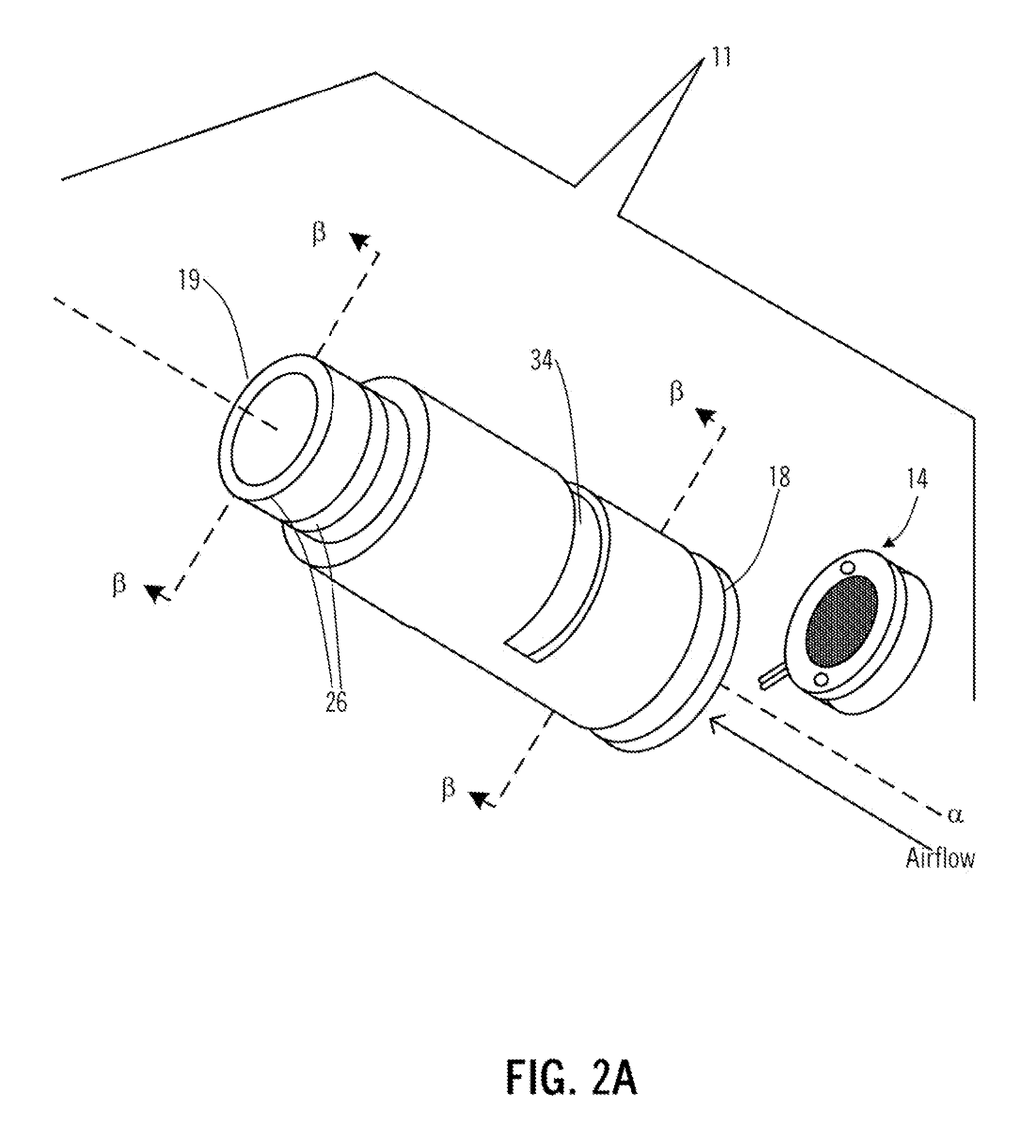
[0025]Yet another object of the invention is to provide a sampling system for both contact and non-contact / non-invasive sampling. A feature of the invention is that brushes, cones or the like can be removably attached to the device by the user in the field, depending on the sampling situation encountered. An advantage of the invention is that depending on the sample tested, the device can be quickly adapted to either contact or contactless sampling, or both in the same sampling period.
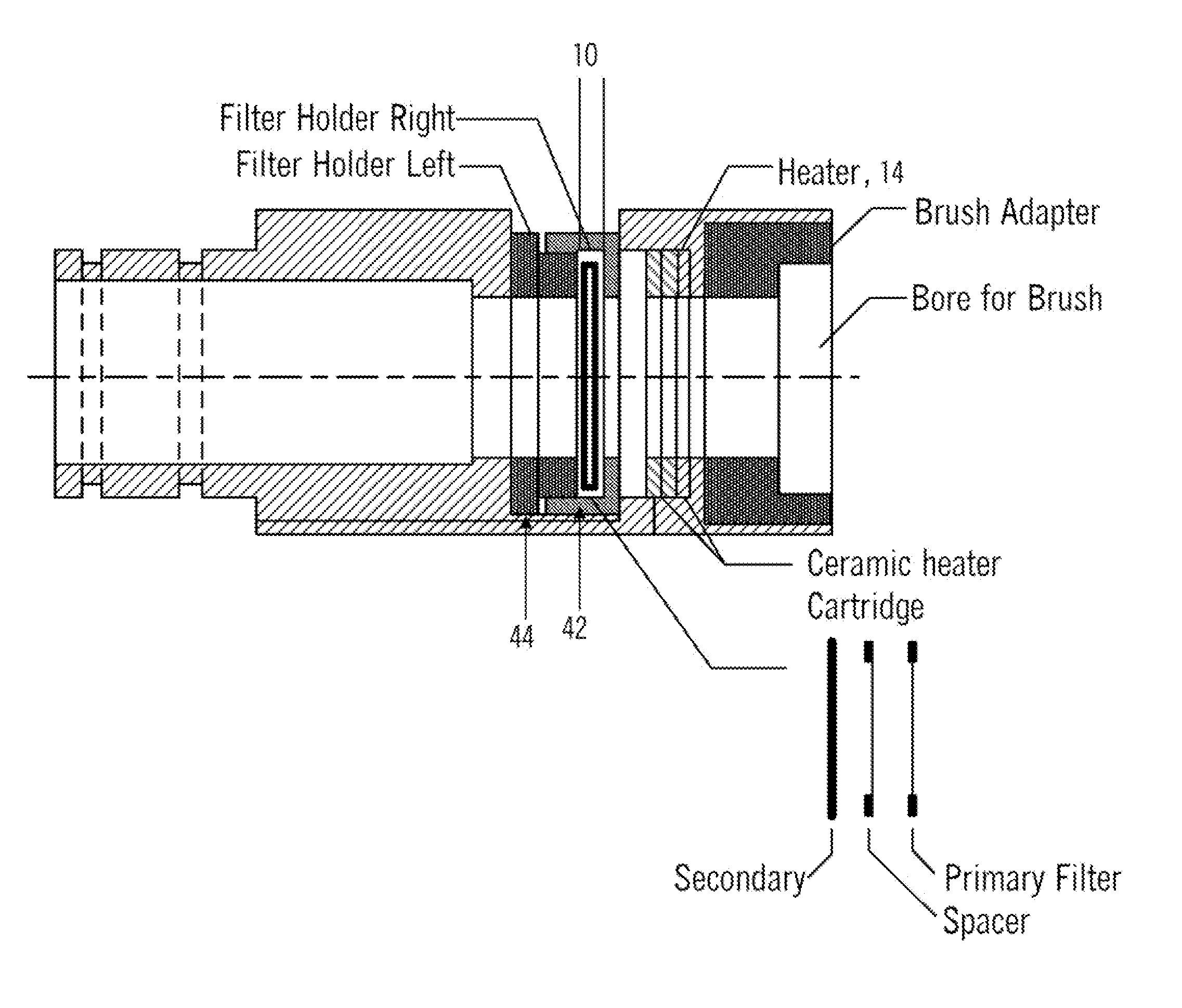
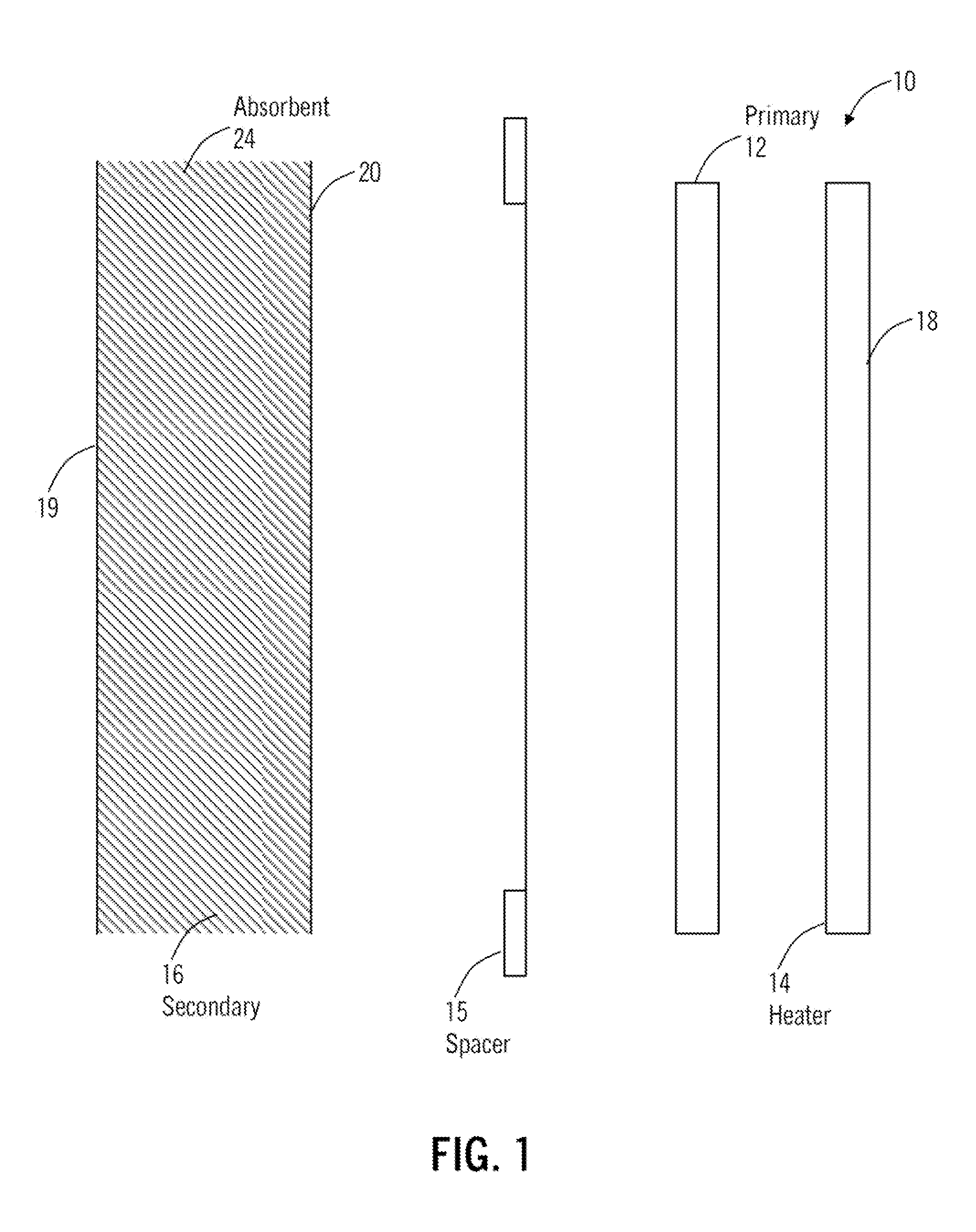
[0026]Still another object of the invention is to provide a sampling system that it provides for desorption of particulate matter to release target compounds of interest. A feature of the invention is that there are two filtering stages, with the second stage physically removable from the presence of the first stage. The primary or first stage filter captures large particles that include the target compounds and unwanted dirt / dust materials. The heating element provides thermal means to desorb target compounds from material that is trapped on the primary filter. These vaporized-compounds will then be re-trapped on the secondary filter. The compounds of interest are pre-concentrated on the secondary filter for eventual analysis.
[0027]A further object of the invention is to provide a completely dry compound detection system. A feature of the invention is that it sequesters compounds of interest in a reversible adsorption process. An advantage of the invention is that the adsorbed compounds remain stable within the secondary filter for at least 10 minutes. Specific retention time will be a function of adsorbent resin and the quantity and physical properties of the trapped-compounds. Stability of the trapped-compounds within the secondary filter will facilitate transport of the secondary filter to a remote site for desorbing the sequestered compounds for identification.
[0028]Yet another option of the invention is providing a detection system with a single adsorption bed. A feature of the system is that the single adsorption bed is removable from the system. An advantage of the system is that the adsorption bed is adapted to sequester a myriad of compounds in solid, liquid and vapor phase for later analysis.

Problems solved by technology

While such sampling devices are reliable, they suffer from many disadvantages, one of which is efficiency.
Generally, in high volume situations it would take too much time to prepare liquid samples for every surface requiring testing.
These systems involve large chambers, and therefore require a large foot print in which to operate.
However, many of these wands are tethered to stationary detection units, thereby hindering an operator's movement when climbing over parcels and crates.
Many of these sampling devices are one-offs, which is to say once they are used, they cannot be regenerated for use again.
Also, many of these devices are specific for certain target moieties, which limits their applicability to a few sampling methods.
Such systems often do not allow for simultaneous extraction and sequestration of solid phase and / or liquid phase samples.
There is no financial incentive for the manufacturers of ETDs to develop a device that can be used universally with prevalent ETDs including those from competing manufacturers.

Method used


Image

  • High volume sampling front end collection device
  • High volume sampling front end collection device
  • High volume sampling front end collection device

Examples


Embodiment Construction

[0042]In describing exemplary embodiments of the high volume sampling device of the present disclosure illustrated in the drawings, specific terminology is employed for the sake of clarity. The claimed invention, however, is not intended to be limited to the specific terminology so selected, and it is to be understood that each specific element includes all technical equivalents that operate in a similar manner to

[0043]The invention provides a front end specimen collection device for use in detecting trace quantities of explosives, pathogens, and other target compounds accomplish a similar purpose in high volume throughput scenarios. The device is adaptable for use with typical detection equipment and analyzers. Sampling rates of the commercial vapor detectors are 1 to 4 Liters per minute in approximately ¼″ ID sample inlet. However, the HVS sampling rates are between about 40 to 400 Liters per minute thru a 1″ ID sampling port. The sample flow rates are a function of the power of t...


PUM

PropertyMeasurementUnit
inner diameteraaaaaaaaaa
temperaturesaaaaaaaaaa

Abstract

A device for sampling surfaces for the presence of compounds is provided, including a housing having a proximal end adapted to receive it negative pressure gradient and a distal end adapted to contact the surfaces; a heating element spaced from the distal end; a primary filter spaced from the heating element; and a secondary filter spaced from the primary filter, the secondary filter removably received by the housing. Also provided is as method for sampling a surface for the presence of compounds, the method including contacting the surface to dislodge the compounds from the surface; capturing first fractions of the compounds with a primary filter while allowing second fractions of the compounds to pass through the primary filter; heating the primary filter to volatilize the first fractions; capturing the volatized first fractions and the second fractions with a secondary filter; and analyzing the secondary filter to identify the compounds.

Description

PRIORITY CLAIM[0001]This Utility Patent Application claims the benefit of U.S. Provisional Application No. 61 / 353,866 filed on Jun. 11, 2010, the entirely of which is incorporated herein.STATEMENT AS TO FEDERALLY SPONSORED RESEARCH[0002]This invention was made with Government support under Contract N-00173-07-C-2055 funded by the U.S. Department of Homeland Security. The Government has certain rights in this invention.BACKGROUND OF THE INVENTION[0003]1. Field of the Invention[0004]This invention relates to a device for high-volume sampling, and more specifically this invention is related to a particle and vapor collection device.[0005]2. Background of the Invention[0006]Sampling devices, specifically those used to screen large number of people or items, have been used for some time. These devices can be found almost anywhere, including government-run office buildings and airports. For example, airports use body scanners, utilizing machines that allow security officers an unobstructe...

Claims


Application Information

Patent Timeline
Patent Type & Authority Patents(United States)
IPC IPC(8): G01N1/22G01N37/00
CPCG01N1/2205G01N1/24G01N1/44
Inventor CHO, INHO
Owner US DEPT OF HOMELAND SECURITY
Why Eureka
Try Eureka