Active roll control system

a technology of active roll control and control device, which is applied in the direction of interconnection system, resilient suspension, vehicle spring, etc., can solve the problems of deterioration of the durability of the motor b>27/b>, and achieve the effect of improving the durability of the motor

Active Publication Date: 2013-11-12
HYUNDAI MOTOR CO LTD
View PDF35 Cites 9 Cited by
  • Summary
  • Abstract
  • Description
  • Claims
  • Application Information

AI Technical Summary

Benefits of technology

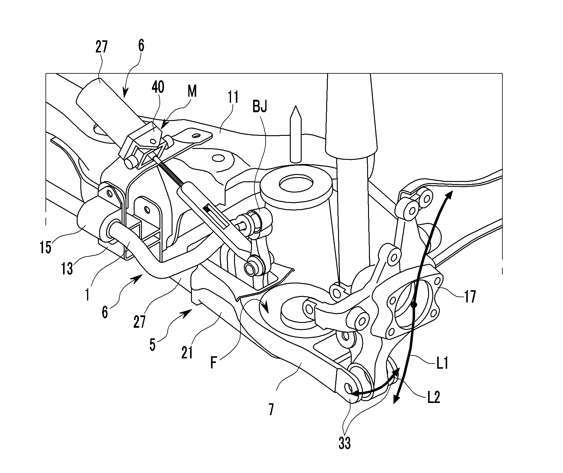
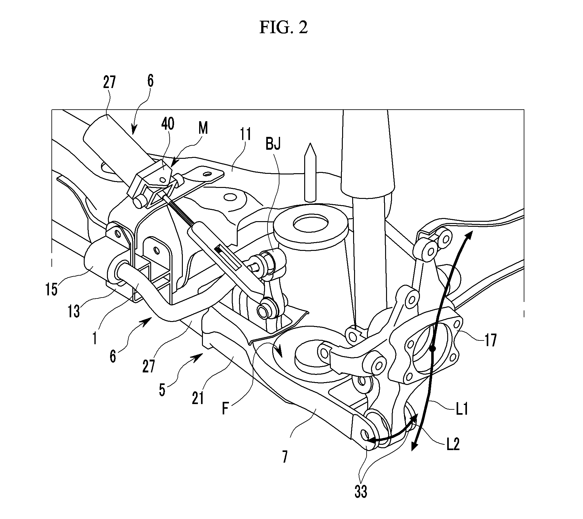
[0021]Various aspects of the present invention provide for an active roll control device having advantages of mounting a motor within a sub-frame such that the motor is not affected by vibration of a vehicle and chipping by gravel to improve the durability thereof.
[0030]Various aspects of the present invention provide for an active roll control device that adjusts a mounting position of the stabilizer link on the suspension arm through a connector of a driving unit operating a motor that is disposed at a lower portion of the suspension arm according to the driving condition of the vehicle to vary a lever ratio of the stabilizer link such that the roll rigidity of the vehicle is actively controlled and the turning stability of the vehicle is improved.
[0031]The motor may be disposed inside the sub-frame to minimize the chipping effect from the vibration of the vehicle and the grave such that the durability of the motor is improved.
[0032]A three-joint mounting portion that includes a universal joint may be applied on the mounting portion of the motor in the sub-frame considering the movement of the suspension arm according to the movement of the vehicle body such that the motor has three-directional freedom with regard to the sub-frame to improve the power delivery efficiency of the motor.

Problems solved by technology

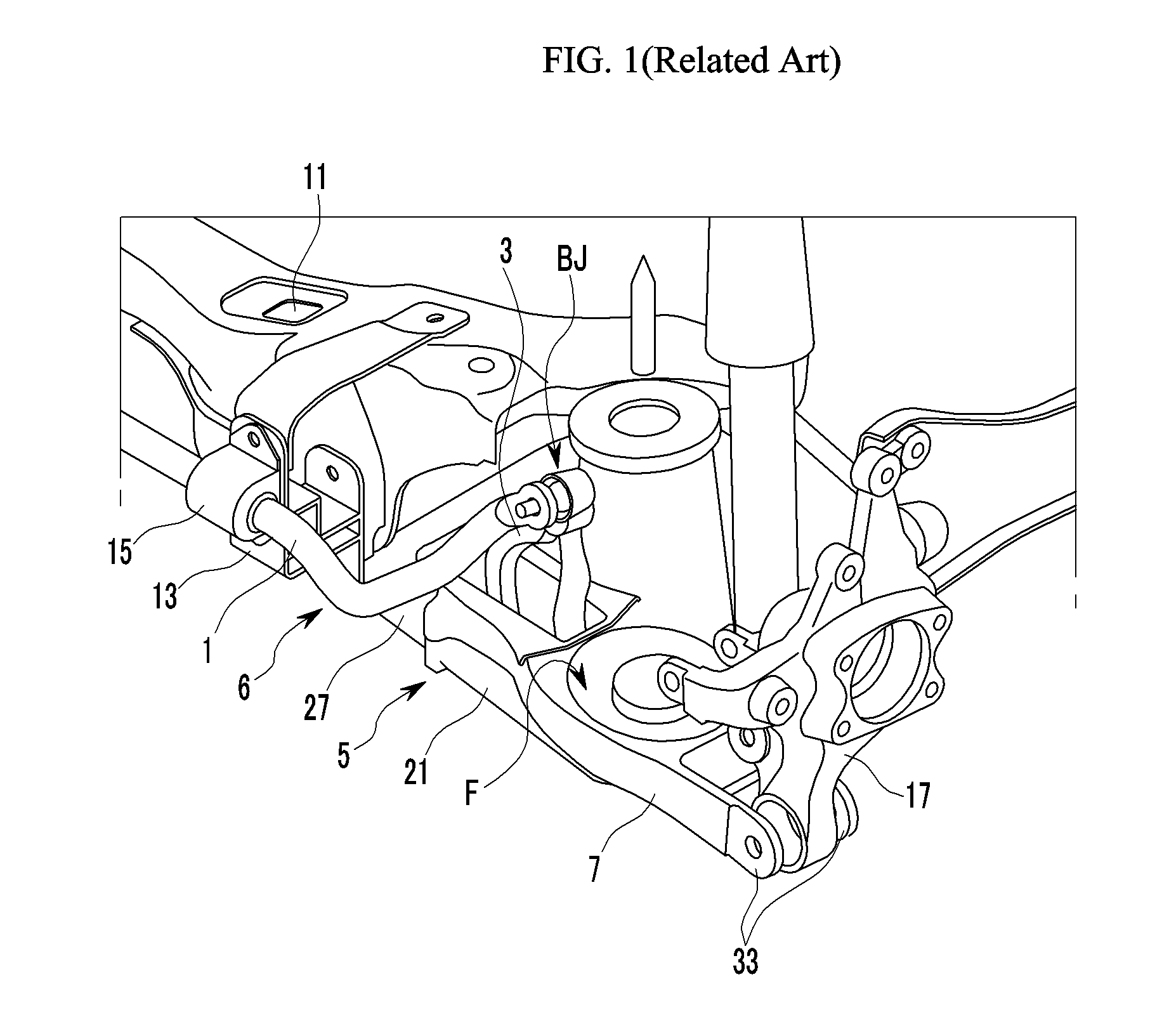
However, the conventional active roll control device has the motor 27 that is disposed on the lower arm 7 and the position of the motor 27 is adversely affected by vibration of a vehicle or a chipping of gravel, and therefore there is a drawback that the durability of the motor 27 is deteriorated.

Method used


Image

  • Active roll control system
  • Active roll control system
  • Active roll control system

Examples


Embodiment Construction

[0039]Reference will now be made in detail to various embodiments of the present invention(s), examples of which are illustrated in the accompanying drawings and described below. While the invention(s) will be described in conjunction with exemplary embodiments, it will be understood that present description is not intended to limit the invention(s) to those exemplary embodiments. On the contrary, the invention(s) is / are intended to cover not only the exemplary embodiments, but also various alternatives, modifications, equivalents and other embodiments, which may be included within the spirit and scope of the invention as defined by the appended claims.

[0040]The drawings and description are to be regarded as illustrative in nature and not restrictive. Like reference numerals designate like elements throughout the specification.

[0041]Also, for convenience, in an exemplary embodiment of the present invention, a left direction is defined as an inside and a right direction is defined as...


PUM


Abstract

An active roll control device varies a position of a stabilizer link connecting a stabilizer bar with a suspension arm such that torsion rigidity of the stabilizer bar is varied to actively control the roll. A penetrating slot is formed in the suspension arm and may include a sliding unit that includes a rail plate disposed in a housing disposed at a lower side of the penetrating slot along a vehicle width direction and connects a connector that is movably disposed on the rail plate with a lower end of the stabilizer link to guide the stabilizer link along a width direction of the vehicle, and a drive unit having a lead screw as a rotation shaft through a three joint mounting portion that engages a screw connector connected to a hinge portion of the stabilizer link to transfer a driving torque to the stabilizer link.

Description

CROSS-REFERENCE TO RELATED APPLICATION[0001]The present application claims priority of Korean Patent Application Number 10-2011-0132869 filed Dec. 12, 2011, the entire contents of which application is incorporated herein for all purposes by this reference.BACKGROUND OF INVENTION[0002]1. Field of Invention[0003]The present invention relates to an active roll control device of a vehicle. More particularly, the present invention relates to an active roll control system (ARCS) that actively controls roll of a stabilizer bar that is disposed at both suspension arms through a stabilizer link.[0004]2. Description of Related Art[0005]Generally, a suspension system of a vehicle connects an axle with a vehicle body, and prevents vibration or impact that is transferred from the road from being transferred to the vehicle body while driving to enhance ride comfort.[0006]The suspension system includes a chassis spring that reduces impact transferred from the road, a shock absorber that dampens a ...

Claims


Application Information

Patent Timeline
Patent Type & Authority Patents(United States)
IPC IPC(8): B60G21/055
CPCB60G17/0162B60G21/0553B60G2204/4232B60G2204/1222B60G2204/423B60G2202/40B60G7/00B60G21/055
Inventor LEE, UN KOOJANG, SUNG BAEJEONG, PIL YOUNG
Owner HYUNDAI MOTOR CO LTD
Why Eureka
Try Eureka