Piezoelectric fan and cooling device

a technology of piezoelectric fans and cooling devices, which is applied in the direction of machines/engines, positive displacement liquid engines, lighting and heating apparatus, etc., can solve the problems that the piezoelectric fan b>10/b> of kaneko cannot sufficiently cool such cpus, and the heat generated by the cpus is increased, so as to achieve the effect of improving the cooling capability of piezoelectric fans and amplitude of blades

Active Publication Date: 2013-11-12
MURATA MFG CO LTD
View PDF17 Cites 6 Cited by
  • Summary
  • Abstract
  • Description
  • Claims
  • Application Information

AI Technical Summary

Benefits of technology

[0013]To overcome the problems described above, preferred embodiments of the present invention provide a piezoelectric fan that achieves an improved cooling capability by improving the airflow generating capability of the blades and improving the ventilation of the grooves between the heat dissipating fins, and a cooling device including such a piezoelectric fan.

Problems solved by technology

Therefore, while the high-density mounting of components leads to reduced ventilation inside the electronic devices, the amount of heat generated by the CPUs is increased.
Unfortunately, the piezoelectric fan 10 of KANEKO cannot sufficiently cool such CPUs.

Method used


Image

  • Piezoelectric fan and cooling device
  • Piezoelectric fan and cooling device
  • Piezoelectric fan and cooling device

Examples


first preferred embodiment

[0042]A cooling device according to a first preferred embodiment of the present invention will be described below with reference to the drawings.

[0043]FIG. 4 is a perspective view showing the configuration of a piezoelectric fan used in the cooling device according to the first preferred embodiment of the present invention. FIGS. 5 and 6 are perspective views showing the configuration of the cooling device. FIG. 7 is a side view showing the configuration of the cooling device disposed on the upper surface of a heat generating body mounted on a circuit board.

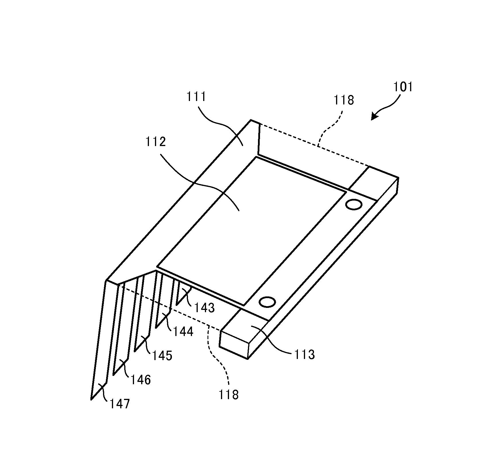
[0044]A piezoelectric fan 101 includes a vibrating plate 111, piezoelectric elements 112, and a supporting plate 113. A heat sink 20 includes a plurality of heat dissipating fins 22 extending from a base portion 21 upward and parallel or substantially parallel to each other. In FIGS. 5 to 7, a heat generating body 50, such as a CPU, for example, is mounted on a circuit board P, and the bottom surface of the heat sink 20 is dispos...

second preferred embodiment

[0063]FIG. 9 is a perspective view of a piezoelectric fan used in a cooling device according to a second preferred embodiment of the present invention. FIG. 10 is a side view showing the configuration of the cooling device disposed on the upper surface of a heat generating body mounted on a circuit board. In FIGS. 5 and 6, the vibrating plate 111 is bent toward the grooves between the heat dissipating fins 22. However, as shown in FIGS. 9 and 10, the vibrating plate 111 may preferably be fixed to a heat sink 30 having a mounting plate 23 provided on the top of the back end thereof, without being bent. In this cooling device 3, the other end of the vibrating plate 111 of the piezoelectric fan 102 is fixed with screws 115 to the mounting plate 23 of the heat sink 20 with the supporting plate 113 disposed therebetween such that the plurality of blades 141 to 147 are located in the grooves between the heat dissipating fins 22 of the heat sink 20 and the cutouts 118 are located over the ...

third preferred embodiment

[0064]FIG. 11 is a perspective view of a piezoelectric fan used in a cooling device according to a third preferred embodiment of the present invention. In FIGS. 5 and 6, a piezoelectric fan 101 including a vibrating plate 111 having cutouts 118 provided therein is fixed to a heat sink 20. However, as shown in FIG. 11, a piezoelectric fan 103 including a vibrating plate 111 having openings 119 provided therein may preferably be fixed to a heat sink 20. In this piezoelectric fan 103, a downward flow of cool air through the openings 119 into the grooves between the heat dissipating fins 22, or an upward flow of air warmed between the heat dissipating fins 22 through the openings 119 is generated.

[0065]It was confirmed that the piezoelectric fan 103 has substantially the same airflow generating capability as the piezoelectric fan 101.


PUM


Abstract

A piezoelectric element is attached to a vibrating plate. By expanding and contracting the piezoelectric element, the vibrating plate is bent. The vibrating plate includes removed regions on both sides of a portion to which the piezoelectric element is attached. The vibrating plate includes a plurality of the blades provided at one end thereof. By bending the vibrating plate, the blades swing. The blades are bent toward grooves between heat dissipating fins of a heat sink. The other end of the vibrating plate is fixed with screws to an upper portion of the heat sink with a supporting plate disposed therebetween such that the each of the blades are located in a groove between the heat dissipating fins of the heat sink and the removed regions are located over the grooves between the heat dissipating fins.

Description

BACKGROUND OF THE INVENTION[0001]1. Field of the Invention[0002]The present invention relates to a piezoelectric fan that discharges warm air between heat dissipating fins of a heat sink, and a cooling device that includes such a piezoelectric fan.[0003]2. Description of the Related Art[0004]For recent electronic devices, countermeasures against heat inside the devices are becoming more important as the size of the device main body is further reduced and the high-density mounting of components progresses. For example, in personal computers, in addition to the size of device main body being reduced, the speed of CPUs is increasing in order to improve information processing performance. Therefore, while the high-density mounting of components leads to reduced ventilation inside the electronic devices, the amount of heat generated by the CPUs is increased. In such an environment, it is important to discharge warm air between heat dissipating fins of a heat sink disposed on the upper su...

Claims


Application Information

Patent Timeline
Patent Type & Authority Patents(United States)
IPC IPC(8): H01L41/08
CPCF04D33/00H01L23/467H01L2924/0002H01L2924/00
Inventor TANAKA, NOBUHIRA
Owner MURATA MFG CO LTD
Why Eureka
Try Eureka