Method for adjusting the amount of marking material in a printed image

a technology of marking material and printed image, which is applied in the field of adjusting the amount of marking material in printed images, can solve the problems of not being able to change the appearance or characteristics of images, and the complexity of electronic circuits, so as to reduce the amount of marking material

Active Publication Date: 2013-11-12
OCE TECH
View PDF6 Cites 0 Cited by
  • Summary
  • Abstract
  • Description
  • Claims
  • Application Information

AI Technical Summary

Benefits of technology

[0011]In an embodiment, the print pixels for which no marking material will be applied are arranged in a regular pattern. This has the advantage that graininess in the printed image is avoided.
[0017]In another embodiment, the level of reducing the amount of marking material is selected by a user by selecting one of a set of at least two available masks. In this embodiment, the user is given control over the quality of the print in relation to the amount of marking material that is to be used, and thus provides additional control for the image processing of the binary image.
[0018]The invention may be embodied in a print engine that is configured to print a binary image by a print process, the print engine comprising a module for filtering the print signal associated with the binary image by a mask that reduces the amount of marking material that is to be used in the print process according to one of the previously mentioned methods.

Problems solved by technology

However, once a binary image is transmitted to the print engine, it is usually not possible anymore to change the appearance or characteristics of the image.
In some print processes, it is necessary to reduce the amount of marking material, since the receiving material is unable to handle the maximum amount that may be applied locally.
This selection mechanism leads to rather complicated electronic circuits.

Method used


Image

  • Method for adjusting the amount of marking material in a printed image
  • Method for adjusting the amount of marking material in a printed image
  • Method for adjusting the amount of marking material in a printed image

Examples


Embodiment Construction

[0025]The present invention will now be described with reference to the accompanying drawings, wherein the same reference numerals have been used to identify the same or similar elements throughout the several views.

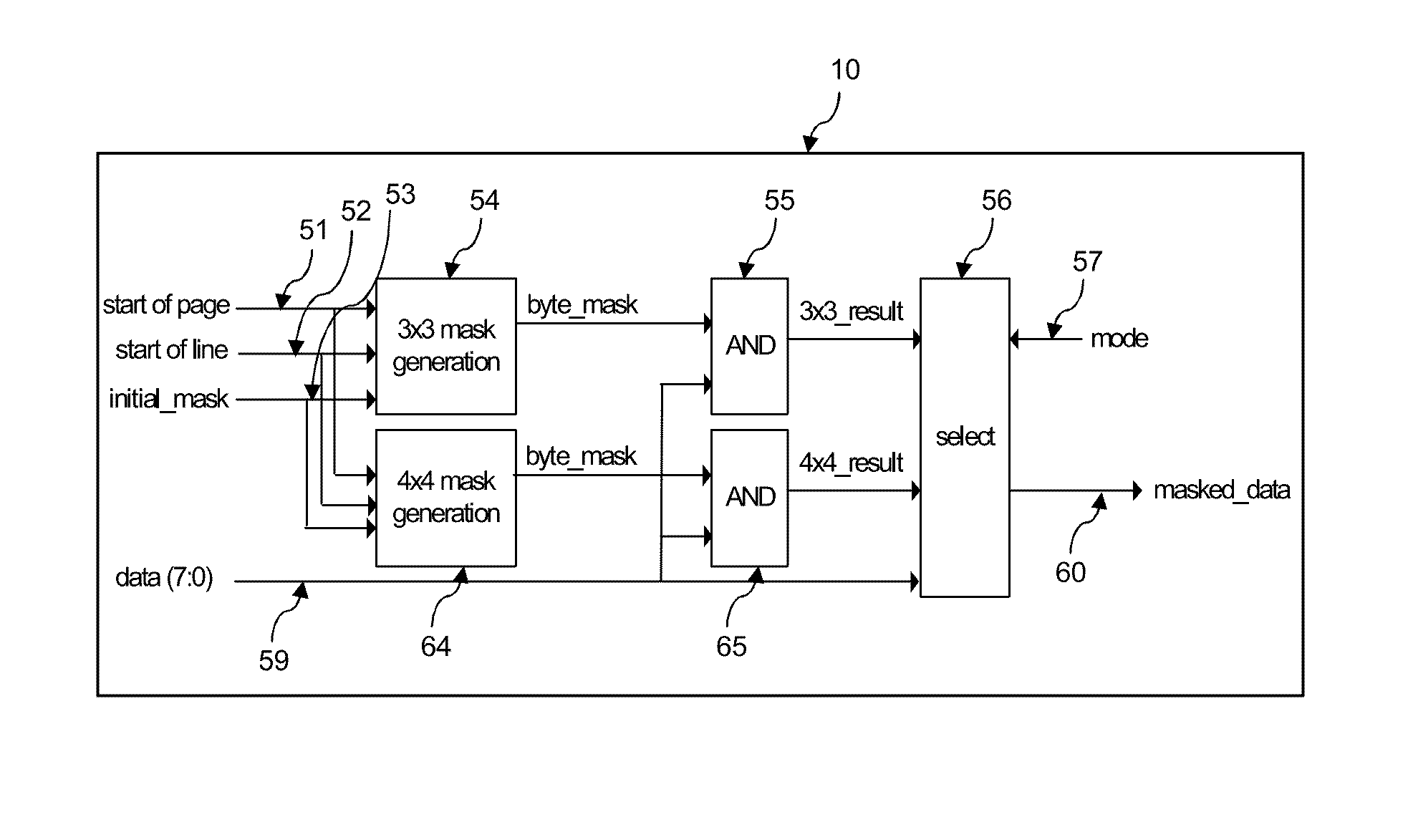
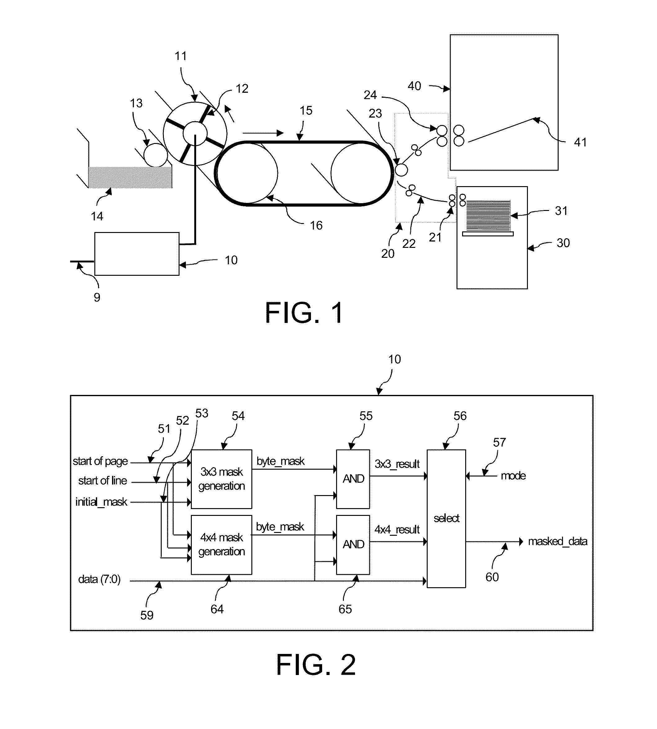
[0026]FIG. 1 shows a print engine for printing binary images. The print engine comprises a converter 10 to convert image data into print signals, an image forming module 11 to apply marking material corresponding to the print signal, the marking material being brought in contact with the image forming module by a developing roller 13, a transfer module 15 for transferring the marking material to the image fixing module 20, a receiving material input module 30 and a finished output product module 40. In this embodiment, the marking material is conventionally toner, which comprises a resin that is softened by heat.

[0027]The binary image data are supplied to the print engine through a data connection 9. This may be a conventional USB- or Firewire-bus or any other suitable d...


PUM


Abstract

A method for reducing an amount of marking material for printing a binary image on a receiving material uses a printing process configured to apply print pixels and to associate each image pixel with at least two print pixels. A print signal is generated indicating for each print pixel whether marking material is to be applied. The print signal is filtered by a predefined mask that defines for which print pixels no marking material will be applied independent of the pixel value of the associated image pixel. The print pixels that are blocked by the mask define a regular pattern to avoid graininess in the printed image. The main effect on print quality is a reduction of the contrast in the image. By choosing one of a set of at least two masks, the user selects the amount of reduction that is realized in the print process.

Description

BACKGROUND OF THE INVENTION[0001]1. Field of the Invention[0002]The present invention relates to a method for reducing an amount of marking material to be used for printing an image on a receiving material using a print process. The present invention further relates to a print engine, configured to perform said method.[0003]2. Description of the Related Art[0004]Many known print processes for reproducing documents and images are arranged to work with a binary print signal that indicates whether or not a fixed amount of marking material is to be applied for a predefined print pixel. The marking material is for example toner or ink. The print pixels are regularly distributed on a receiving material. In color print processes, several process colors are used to obtain a full color output, each of the process colors being developed individually by an associated binary print signal.[0005]A binary image is usually a two-dimensional array of pixels, wherein each image pixel has one of two v...

Claims


Application Information

Patent Timeline
Patent Type & Authority Patents(United States)
IPC IPC(8): G06K15/02H04N1/46B41J2/47
CPCG06K15/107G06K15/1869G06K2215/0074
Inventor WOERING, JANTINUS
Owner OCE TECH
Why Eureka
Try Eureka