High voltage and frequency distributed power system

a power system and high voltage technology, applied in the direction of dc circuit to reduce harmonics/ripples, dc circuits with intermediate conversion to dc, dc circuits with two wires, etc., can solve the problems of complex stand-by arrangements, and difficult to bring on-line quickly, so as to reduce hardware requirements and improve efficiency and controllability.

Inactive Publication Date: 2013-11-12
LOCKHEED MARTIN CORP
View PDF16 Cites 8 Cited by
  • Summary
  • Abstract
  • Description
  • Claims
  • Application Information

AI Technical Summary

Benefits of technology

[0010]It is therefore an object of the present invention to provide a power distribution system of increased efficiency and controllability with much reduced hardware requirements.

Problems solved by technology

However, much of the efficiency and effectiveness of such systems is based on designs which assume that power demands will fluctuate only slowly at levels approximating an average demand or load with only limited capacity to handle peak loads.
Such stand-by arrangements are often complex and cannot be brought on-line quickly while consuming some amount of power which may be significant.
Such arrangements are also particularly problematic in power distribution systems for vehicles such as aircraft or ships or some special purpose land-based vehicles such as mobile health care or medical screening vehicles or in installations such as health care facilities having sporadically used high-load equipment where the ability to satisfy a peak load may be of high importance if not critical and sources of additional power are likely to be limited (e.g. separately powered generators which cannot be started quickly or which consume considerable fuel in a stand-by state).
Further, in vehicles where external potential sources of excess power generation capacity are not available, there may be the additional criticality of space or weight limitations that, as a practical matter, may preclude power distribution in a conventional manner to answer peak power demands.
Such computers will generally require power at a plurality of different voltages (which may be generated internally from a single voltage input although each conversion carries its own level of inefficiency as well as increasing the size and weight of each of such computers and equipment).
However, the disparity between peak power requirements and stand-by or sleep state power requirements of computers are becoming greater and the gain in space and weight savings is becoming increasingly limited, especially at the load location, due to the need to supply transient power requirements from power conversion devices within limited weight and volume specifications, particularly if the power is supplied from low frequency alternating current due, in part, to stringent regulation requirements.
Accordingly, conventional power distribution system designs are being found to be inadequate, substantially less than optimal or simply not feasible increasingly often.
For example, while a power distribution system of maximum tolerable size and weight for a given application might well accommodate loads well above average loads, the maximum power that can be delivered may be only a relatively small fraction of the potential peak load possible if potential loads are to be concurrently supplied with adequate power while diversion of power from other systems is much less likely to be possible in a vehicle.
Moreover, additional power generation and distribution apparatus of conventional design that might be tolerable to accommodate peak load carry the additional cost of consuming stand-by power or may be brought on line only slowly, which may be deemed inadequate and an unacceptable operational constraint, particularly in vehicles.
Thus, it is seen that conventional power distribution architectures are inadequate for many modern applications.

Method used


Image

  • High voltage and frequency distributed power system
  • High voltage and frequency distributed power system
  • High voltage and frequency distributed power system

Examples


Embodiment Construction

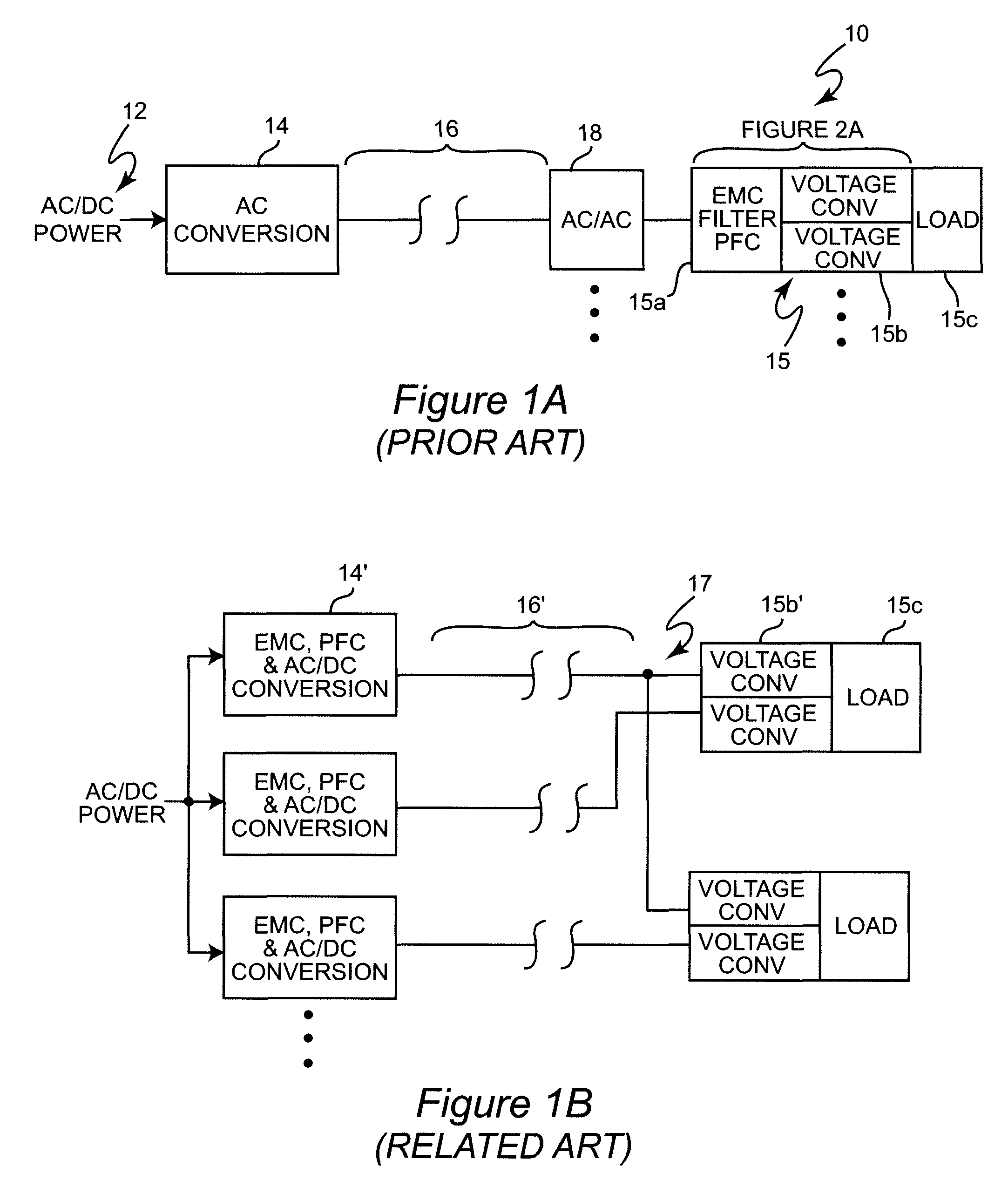
[0021]Referring now to the drawings, and more particularly to FIG. 1A, there is shown a high-level block diagram of a conventional power distribution system widely implemented at the present time. It should be understood that this basic architecture can be and is currently implemented at many levels, as alluded to above, from national or continental power grids to a residential household or even respective portions thereof and thus may vary greatly in design particulars, as will be recognized by those skilled in the art. Thus, input power could correspond to a generator at a commercial power plant or the output of a meter hub at a building or dwelling. AC conversion 14 may be sequentially provided at a variety of locations depending on applications and most particularly in consideration of the distance over which power is to be carried by cable 16. Similarly AC / AC conversion 18 may be provided sequentially several times to isolate or step the voltage down to some standard level such...


PUM


Abstract

A switching power supply transmits power between a single front end including electromagnetic interference filtering and power factor correction circuits to an output end at a high voltage and high frequency from which any desired DC voltage or waveform may be readily and directly derived with high efficiency in order to reduce size and weight of components including transformers at the output end and allow greater variety of connection wiring of reduced weight and volume to be used. The high frequency is limited at the low frequency end by the frequency at which significant power can be transferred through, for example, a ferrite core or other transformer of sufficiently low volume to accommodate closely spaced loads or power converters and at the high frequency end by the wavelength in the connection wiring such that 1 / 10 wavelength is greater than one thousand feet. Branches of the power distribution system which are not desired to be in use can be operated at zero power and be brought back on line within milliseconds, when needed. Power distribution among respective branches of the power distribution system can be controlled by varying the high frequency of power transmission and appropriate filtering.

Description

BACKGROUND OF THE INVENTION[0001]1. Field of the Invention[0002]The present invention generally relates to power distribution systems and, more particularly to power distribution systems for distribution of power less than approximately 1000 feet from the power source connection and having reduced hardware requirements while exhibiting enhanced power conservation.[0003]2. Description of the Prior Art[0004]The use of electrical power has become substantially ubiquitous in most aspects of modern life. Accordingly, power distribution systems at many levels such as regions of a national or continental power grid, large industrial plants, building complexes, individual buildings such as offices, hospitals, apartments, homes and the like or even vehicles such as ships or aircraft are familiar and, until fairly recently, designs have been well-optimized to provide power in virtually all applications where power is needed. Such power distribution systems generally operate at standardized vo...

Claims


Application Information

Patent Timeline
Patent Type & Authority Patents(United States)
IPC IPC(8): H02J3/00
CPCH02J1/06H02J2001/002H02J1/002
Inventor KALMS, WILLIAMMORBER, JOHNASBELL, ROBERT
Owner LOCKHEED MARTIN CORP
Why Eureka
Try Eureka