Method for operating a metal detection system and metal detection system

a metal detection system and metal detection technology, applied in the direction of magnetic field magnitude/direction, measurement devices, instruments, etc., can solve the problems of insufficient measurement, low efficiency, and considerable effort, and achieve the effect of improving the sensitivity of the metal detection system, reducing efforts, and high efficiency

Active Publication Date: 2013-11-19
METTLER TOLEDO SAFELINE LTD
View PDF108 Cites 34 Cited by
  • Summary
  • Abstract
  • Description
  • Claims
  • Application Information

AI Technical Summary

Benefits of technology

[0024]An exemplary embodiment of the method may therefore allow obtaining optimal transmitter frequencies with which the smallest possible particles of one or more metal contaminant types may be detected. Accordingly, an example of a metal detection system may optimally be configured for any measurement, involving products of any consistency and any potential metal contaminant type.
[0025]In an exemplary embodiment, measuring a product at unsuitable transmitter frequencies and analyzing the related data may be avoided. One exemplary embodiment of the method may always apply the optimal frequencies so that measurements are performed with reduced efforts and high efficiency. For example, since measurements are not performed at unsuitable transmitter frequencies, the time available for measuring a product, i.e., for detecting metal contaminants in a product, is dedicated to the application of one or more optimal transmitter frequencies. As a result, more measurement data of high-quality is available for an individual metal contaminant. In an exemplary embodiment, this consequently leads to a significant improvement of the sensitivity of the metal detection system for all products and metal contaminant types measured. Optimal transmitter frequencies may therefore be determined for all metal contaminant types that may occur in a product and for all available products for all transmitter frequencies that may be selected.
[0029]For this purpose in an exemplary embodiment, for each transmitter frequency a second array may be built with curves of different metal contaminant types recorded with the same transmitter frequency. Then for a specific transmitter frequency a superposition of a second array and the product information may be arranged, which allows determining which parts of the curves lie within or outside of the area or range of the product signals. In an example, parts of the curves that lie outside the range of the product signals indicate particle sizes of the metal contaminant, which may not be masked or suppressed together with the product signals.
[0030]Hence, an exemplary embodiment of the method and the metal detection system may not only allow determining the optimal transmitter frequency of a metal contaminant but also allow determining the minimum particle sizes of the metal contaminant types that may be detected. This valuable information may be used for configuring an example of the metal detection system to operate most efficiently.

Problems solved by technology

Consequently, the result of the measurement will not be optimal.
Hence, this method, which requires considerable efforts in the signal processing stages, is characterized by a relatively low efficiency.
Moreover, such metal detection systems that operate at different frequencies typically have a low sensitivity.
Hence, although signals of metal contaminants may be obtained with a desirable phase, the detection of these signals may still fail due to the low sensitivity of such metal detection systems.

Method used


Image

  • Method for operating a metal detection system and metal detection system
  • Method for operating a metal detection system and metal detection system
  • Method for operating a metal detection system and metal detection system

Examples


Embodiment Construction

)

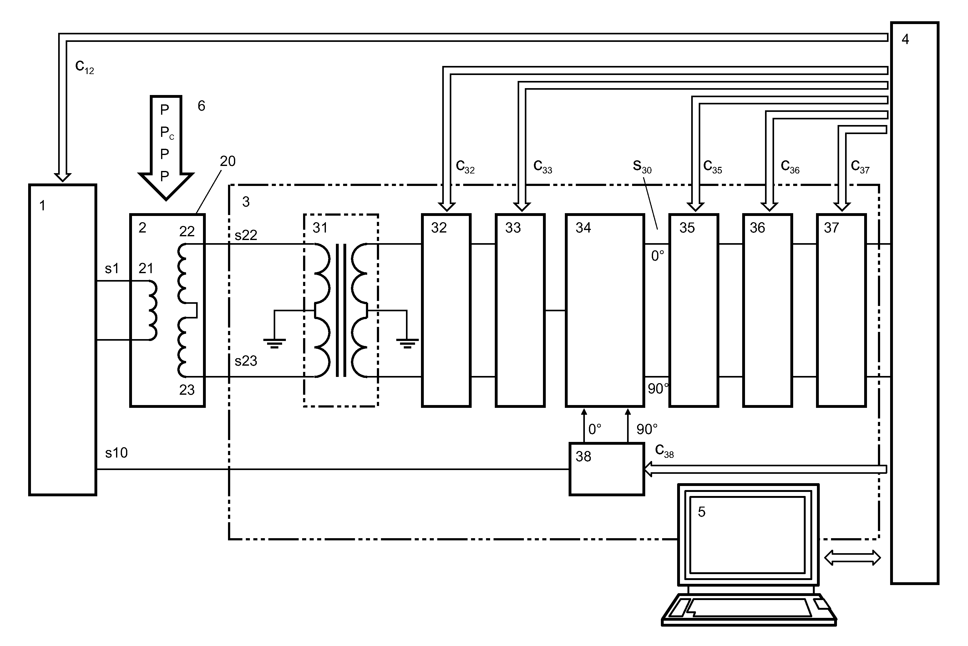
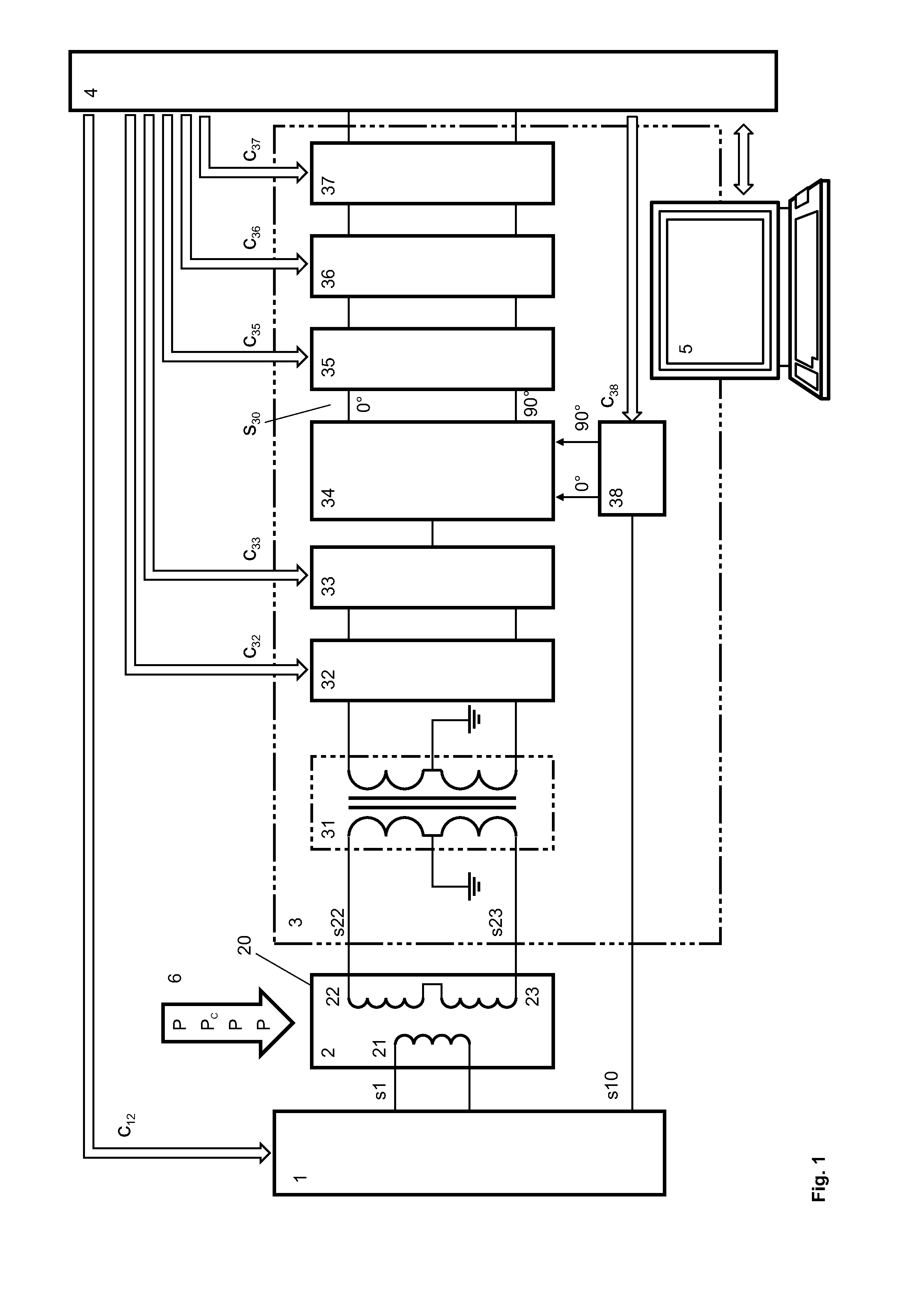
[0048]FIG. 1 shows a block diagram of an exemplary embodiment of a metal detection system, which comprises a transmitter unit 1, a balanced coil system 2 with a transmitter coil 21 and a first and a second receiver coil 22, 23, a receiver unit 3, a signal processing unit 4, and a control unit 5 that comprises standard interfaces, input devices, and output devices, particularly a monitor. FIG. 1 further shows a conveyor 6, on which products P are transferred through the transmitter coil 21 and the receiver coils 22, 23.

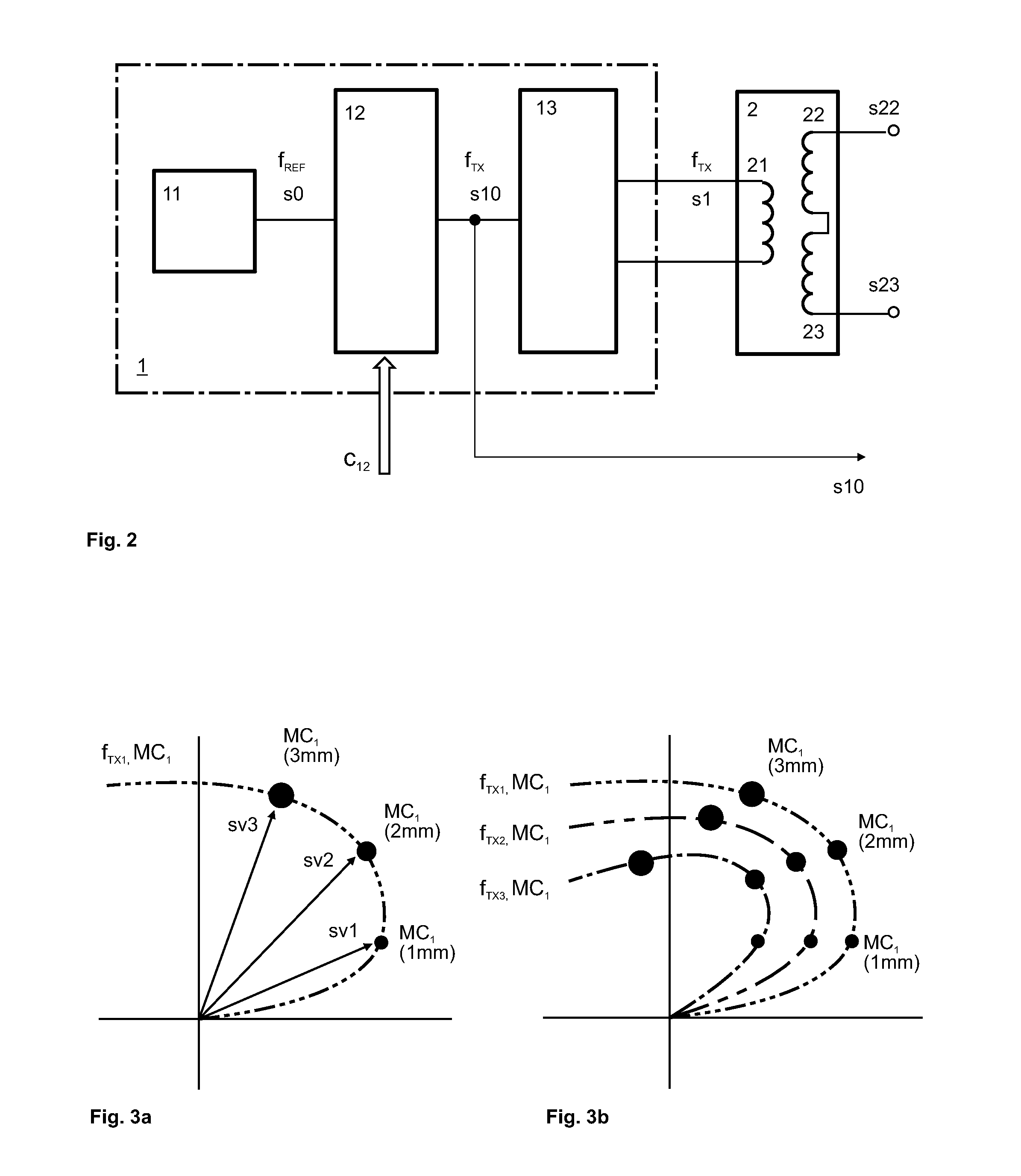
[0049]The transmitter unit 1, for which an exemplary embodiment is shown in detail in FIG. 2, provides a transmitter signal s1 to the transmitter coil 21 of the balanced coil system 2. Further, the transmitter unit 1 provides a reference signal s10 having the transmitter frequency fTX to the receiver unit 3.

[0050]In an exemplary embodiment, the transmitter signal s1 induces signals s22, s23 in the identical receiver coils 22, 23 that are of the same magnitude but inve...


PUM


Abstract

A method for operating a metal detection system that comprises a balanced coil system. One embodiment of the method comprises: determining the phase and magnitude of related signals at least for a first metal contaminant for at least two transmitter frequencies and for at least two particle sizes of the first metal contaminant; determining the phase and magnitude of the related signal for a specific product for the at least two transmitter frequencies; comparing information established at least for the first metal contaminant and the information established for the product; determining a transmitter frequency with which signal components of smallest sized particles of the at least first metal contaminant differ sufficiently or most in phase and amplitude from the phase and amplitude of the product signal; and selecting the transmitter frequency for measuring the product. A metal detection apparatus adapted to operate according to an exemplary method is also provided.

Description

[0001]This application claims priority under 35 U.S.C. §119 to European Patent Application No. 10186895.8, filed Oct. 7, 2010, which is hereby incorporated by reference in its entirety.BACKGROUND AND SUMMARY OF THE INVENTION[0002]Exemplary embodiments of the present invention relate to a method for operating a metal detection system that uses at least two operating frequencies and to a metal detection system that implements this method.[0003]An industrial metal detection system may be used to detect and reject unwanted metal contamination. When properly installed and operated, it will help reduce metal contamination and improve food safety. Most modern metal detectors utilize a search head comprising a “balanced coil system.” Detectors of this design may be capable of detecting all metal contaminant types including ferrous, nonferrous, and stainless steels in a large variety of products such as fresh and frozen products.[0004]A metal detection system that operates according to the “...

Claims


Application Information

Patent Timeline
Patent Type & Authority Patents(United States)
IPC IPC(8): G01R33/02G01R33/00
CPCG01V3/107
Inventor DERUNGS, MAX
Owner METTLER TOLEDO SAFELINE LTD
Why Eureka
Try Eureka