
Patient bed, local coil arrangement and method to determine the position of local coils in a magnetic resonance apparatus

a technology of local coils and magnetic resonance tomography, which is applied in the direction of instruments, nuclear engineering, and using reradiation, can solve the problems of time-consuming and error-prone sighting, and achieve the effect of reducing the risk of sighting, reducing the accuracy of reflection, and reducing the difficulty of detection

Inactive Publication Date: 2013-11-19
SIEMENS HEALTHCARE GMBH
View PDF13 Cites 6 Cited by
  • Summary
  • Abstract
  • Description
  • Claims
  • Application Information

AI Technical Summary

Benefits of technology

[0008]In contrast to manually determining the position by means of a laser cross-hair, the bed table according to the invention thus itself incorporates position determination components themselves. This avoids involvement of an operator / technician prior to the use of the magnetic resonance tomography system, which increases the security with regard to operating errors and the speed of the measurement process. The laser cross-hair (which can be quite uncomfortable for a patient) can also be omitted.
[0009]In an embodiment that makes use of radio-technology for identification of the position, the arrangement according to the invention exhibits the advantage of being more precise and insensitive to reflections than multiple path propagation. This can be achieved by a cable-connected or fiber-connected position determination component that itself is embodied in the fastener.
[0010]Furthermore, compared to position determination by means of a laser cross-hair, the invention exhibits the advantage that subsequent position changes of the coil that, for example, are due to movements of the patient, can be measured and taken into account. Coverage of the patient (for example with a blanket for warming) is possible without any problems without hindering the position determination.
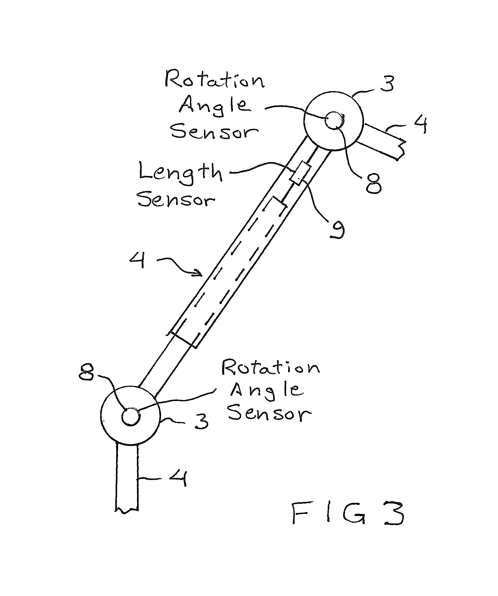
[0015]The coil arrangement can include a combination of pivot bearings and / or ball-and-socket bearings for positioning the coil, which bearings enable the alignment of (for example) telescoping devices. An exemplary combination composed of three pivot bearings and three rods (of which at least two are variable in length in the manner of a telescope) allows a nearly free positioning of the coil over the bed table.
[0017]The position detector in the coil arrangement can include at least one optical sensor and at least one optical waveguide. With optical sensors it can be most easily ensured that no magnetic interaction occurs, and thus also no mutual interferences of position determination and magnetic resonance measurement are to be expected.

Problems solved by technology

It is disadvantageous that such a sighting is error-prone and time-consuming under the circumstances.

Method used


Image

  • Patient bed, local coil arrangement and method to determine the position of local coils in a magnetic resonance apparatus
  • Patient bed, local coil arrangement and method to determine the position of local coils in a magnetic resonance apparatus
  • Patient bed, local coil arrangement and method to determine the position of local coils in a magnetic resonance apparatus

Examples


Embodiment Construction

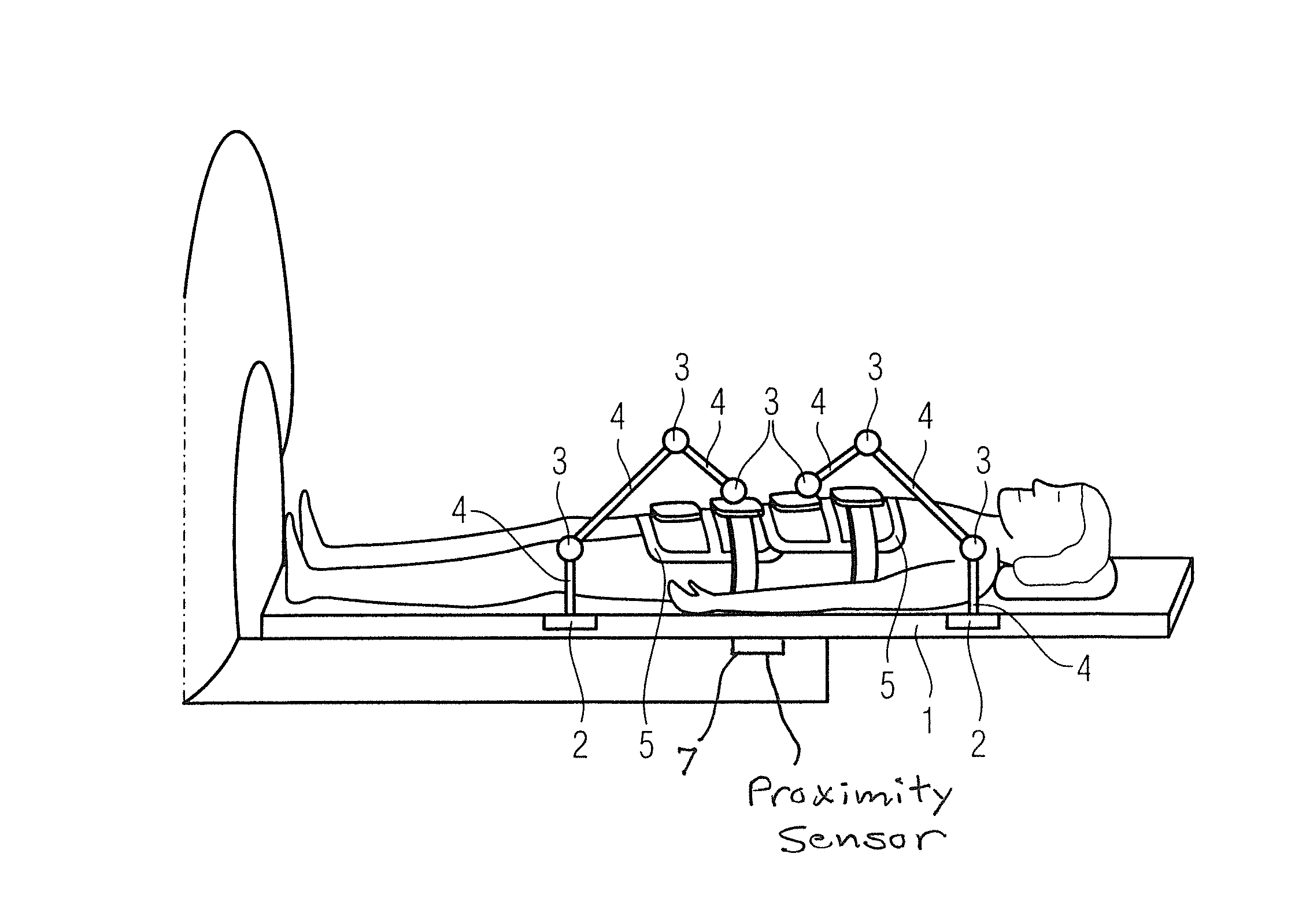
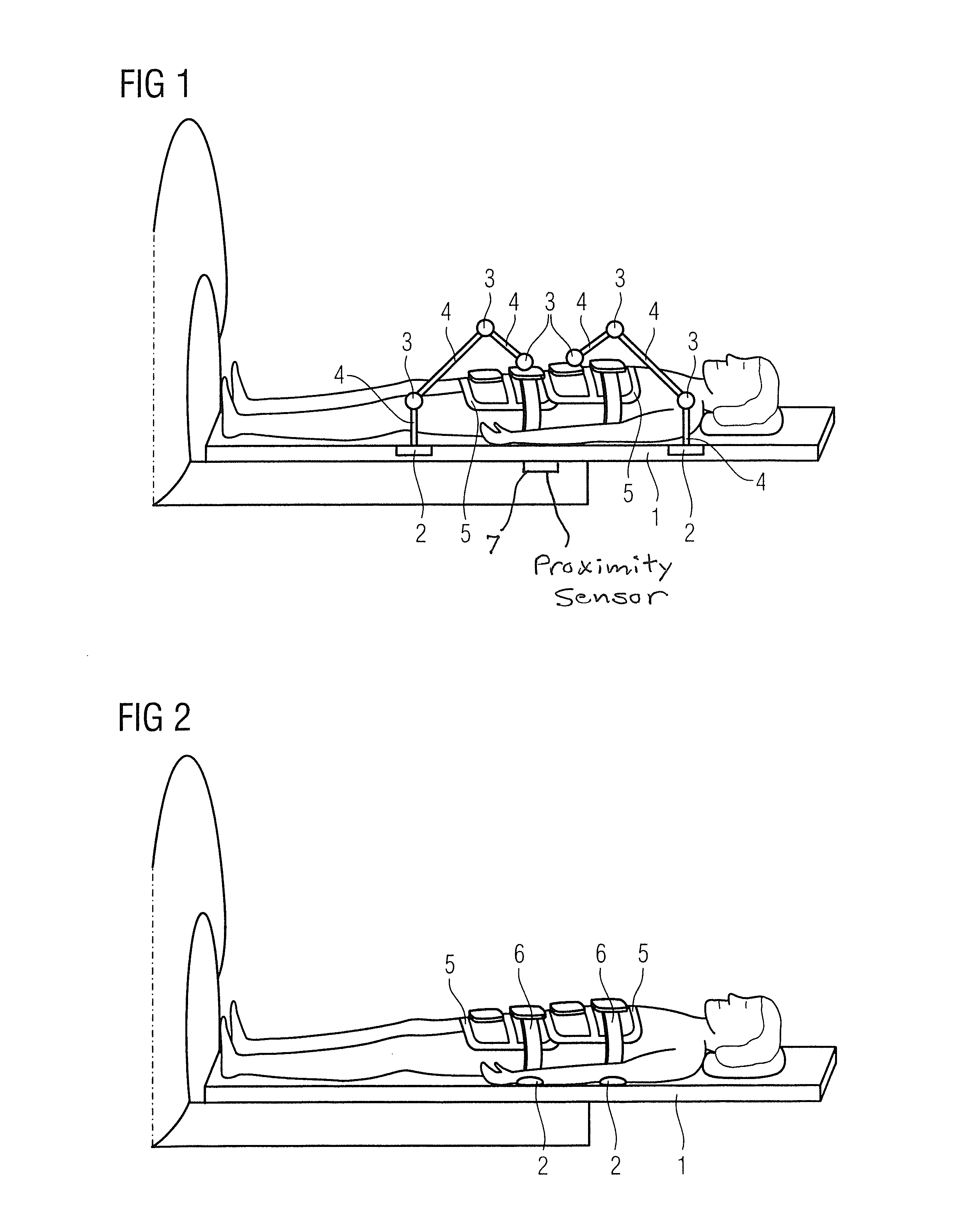
[0022]FIG. 1 shows a person who lies on the bed table 1 of an MR system. Two coils, what are known as body matrix coils 5, are placed on his body. The coils 5 are fastened on respective telescoping arm systems and are positioned by the telescoping arm systems. Each telescoping arm system in this exemplary embodiment has three ball-and-socket joints 3. At least some of the ball-and-socket joints 3 can be replaced by revolute joints. The ball-and-socket joints 3 are connected with one another by means of telescoping rods 4. The connection made up of telescoping rods 4 and the ball-and-socket joints 3 allows the corresponding coil 5 to be very flexibly placed in three dimensions on the body of the patient to be examined.

[0023]In this exemplary embodiment the position of the coil 5 is now determined. Instead of occurring via a manual sighting by means of a laser cross-hair, this occurs via multiple additional elements in the telescoping arm system. In this exemplary embodiment the faste...


PUM


Abstract

At least one non-stationary coil in a magnetic resonance tomography system is attached with a fastener to a displaceable bed. The fastener has a position detector incorporated therein to determine the position or a component of the position of the non-stationary coil. The portion of the position is, for example, the position along the axis of symmetry of the measurement tube.

Description

BACKGROUND OF THE INVENTION[0001]1. Field of the Invention[0002]The present invention concerns methods and devices to determine or detect the position of local coils in a magnetic resonance tomography system.[0003]2. Description of the Prior Art[0004]In addition to stationary acquisition coils (for example shoulder array coils), non-stationary acquisition coils (for example body matrix coils) are also used in magnetic resonance (MR) tomography. During the measurement, the measurement coils are moved into the isocenter of the measurement tube. For this purpose, the position of the tube (primarily along the axis of symmetry of the measurement tube) is determined by sighting with a laser cross-hair. It is disadvantageous that such a sighting is error-prone and time-consuming under the circumstances.SUMMARY OF THE INVENTION[0005]An object of the present invention is to provide a design and a method that allow an improved position determination of non-stationary coils in an MR system. In...

Claims


Application Information

Patent Timeline
Patent Type & Authority Patents(United States)
IPC IPC(8): G01V3/00
CPCG01R33/34007G01R33/3415
Inventor BIBER, STEPHANMAIER, CARL UDOOSTERMAIER, JOCHENSEEMANN, KAY UWE
Owner SIEMENS HEALTHCARE GMBH
Learn More