Apparatus and system for transformer frequency control

a transformer frequency control and apparatus technology, applied in the direction of electric variable regulation, process and machine control, instruments, etc., can solve the problems of inefficiency with respect to time, prior art methods previously mentioned, and prior art implementations that do not specify mppt implementation methods, etc., to maximize power transfer, maximize power transfer, and maximize power transfer

Inactive Publication Date: 2013-11-19
DENG QI
View PDF5 Cites 4 Cited by
  • Summary
  • Abstract
  • Description
  • Claims
  • Application Information

AI Technical Summary

Benefits of technology

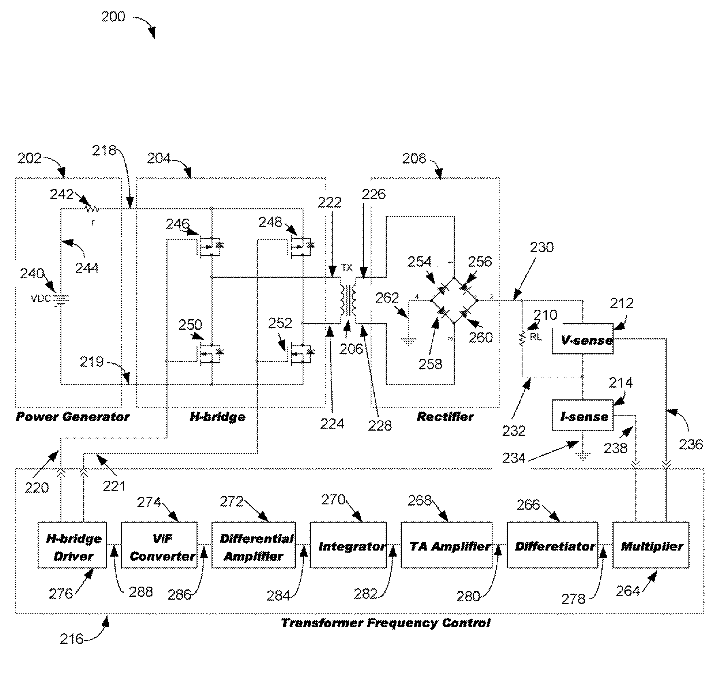
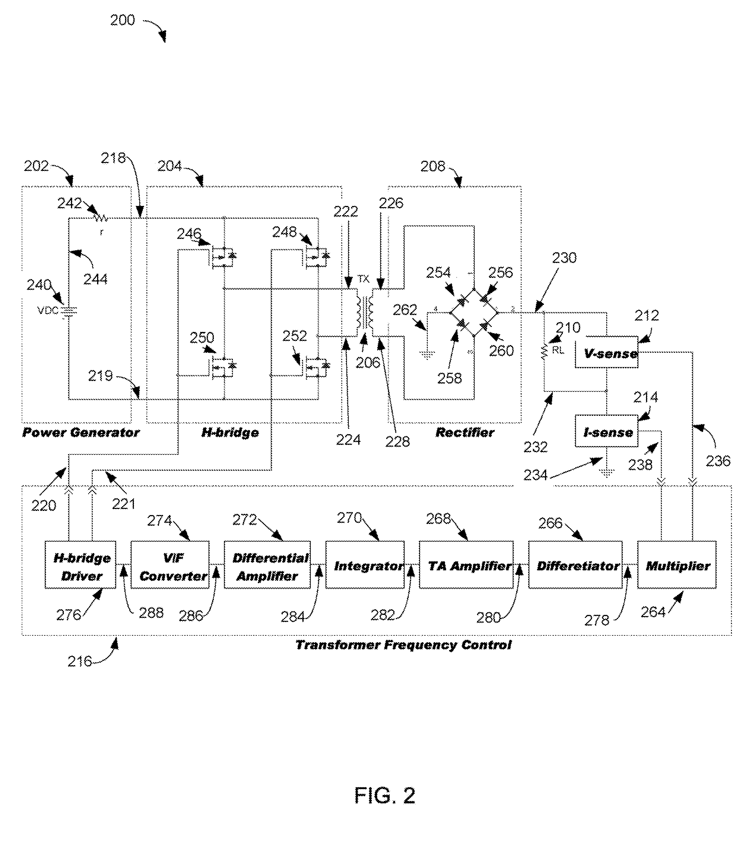
[0022]In one embodiment an apparatus includes means for receiving a sensed voltage of a voltage applied to a load resistance and a sensed current of a current passing through the load resistance where the voltage is a rectified voltage from a transformer's output whose input is from a DC-to-AC power converter being supplied from a DC power generator having an internal resistance, the means being operable to output a product of the sensed voltage and the sensed current. Means receives the product and is operable for outputting a rate of change of the product. Means receives the rate of change and is operable for outputting an integrated voltage indicating an accumulative rate of change of the product. Means receives the integrated voltage and is operable for generating a voltage waveform having a frequency determined by the integrated voltage. Means receives the voltage waveform and is operable for using the voltage waveform to output a control signal for controlling a frequency of the DC-to-AC power converter where the apparatus substantially matches an input resistance of the transformer to the internal resistance, thereby maximizing power transfer to the load resistance.
[0023]In another embodiment an apparatus includes a multiplier circuit operable for receiving a sensed voltage of a voltage applied to a load resistance and a sensed current of a current passing through the load resistance where the voltage is a rectified voltage from a transformer's output whose input is from a DC-to-AC power converter being supplied from a DC power generator having an internal resistance, the multiplier being further operable to output a product of the sensed voltage and the sensed current. A differentiator circuit is coupled to the multiplier circuit and operable for outputting a rate of change of the product. An integrator circuit is coupled to the differentiator circuit and operable for outputting an integrated voltage indicating an accumulative rate of change of the product. A voltage-to-frequency converter circuit is coupled to the integrator circuit and operable for generating a voltage waveform having a frequency determined by the integrated voltage. A driver circuit is coupled to the voltage-to-frequency converter circuit and operable for using the voltage waveform to output a control signal for controlling a frequency of the DC-to-AC power converter where the apparatus substantially matches an input resistance of the transformer to the internal resistance, thereby maximizing power transfer to the load resistance.
[0024]In another embodiment a system includes a DC-to-AC power converter operable for receiving DC power from a power generator having an internal resistance and operable for outputting an AC power. A transformer is coupled to the DC-to-AC power converter and operable for outputting a transformed AC power. A rectifier circuit is coupled to the transformer and operable for outputting a rectified transformed AC power for application to a load resistance. Means senses a voltage on the load resistance and outputs the sensed voltage. Means senses a current through the load resistance and outputs the sensed current. A multiplier circuit is operable for receiving the sensed voltage and the sensed current, the multiplier being further operable to output a product of the sensed voltage and the sensed current. A differentiator circuit is coupled to the multiplier circuit and operable for outputting a rate of change of the product. An integrator circuit is coupled to the differentiator circuit and operable for outputting an integrated voltage indicating an accumulative rate of change of the product. A voltage-to-frequency converter circuit is coupled to the integrator circuit and operable for generating a voltage waveform having a frequency determined by the integrated voltage. A driver circuit is coupled to the voltage-to-frequency converter circuit and operable for using the voltage waveform to output a control signal for controlling a frequency of the DC-to-AC power converter where the system substantially matches an input resistance of the transformer to the internal resistance, thereby maximizing power transfer to the load resistance.

Problems solved by technology

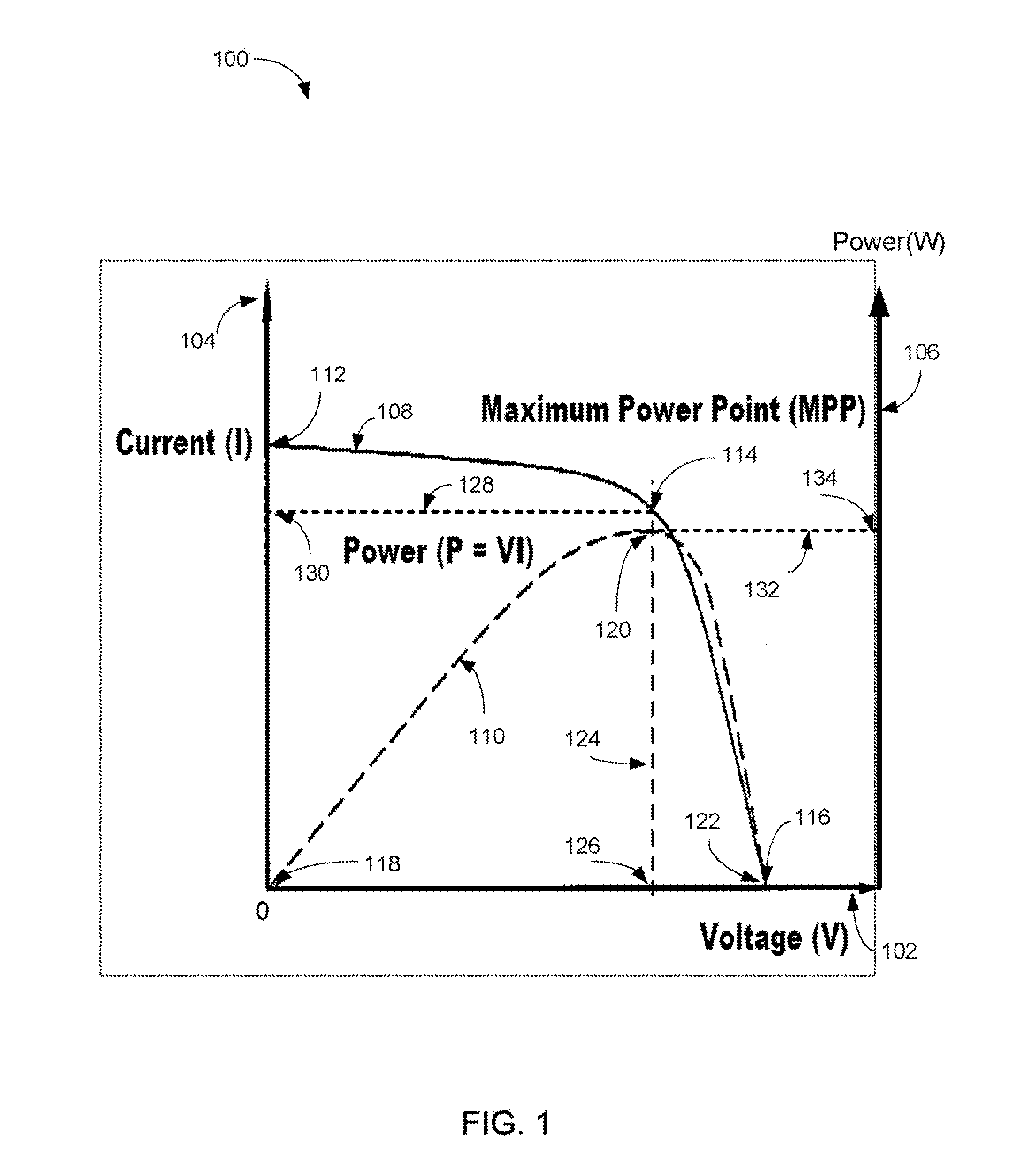
Furthermore, because of the non-continuous nature of digital electronics, it may be inefficient with respect to time for the operating point of the renewable power generator to converge to MPP.
However, the prior art method previously mentioned is limited in that, only a specific load type, such as an AC electrical motor in the case of U.S. Pat. No. 4,494,180, can benefit from the method, and therefore more generic methods are needed to accommodate a diversity of load types.
Furthermore, prior art implementations do not offer detailed implementations that specify methods of MPPT, and more importantly, methods of adjusting the load resistance based on the results of the MPPT in order to match the internal resistance of the renewable power generator.

Method used


Image

  • Apparatus and system for transformer frequency control
  • Apparatus and system for transformer frequency control
  • Apparatus and system for transformer frequency control

Examples


Embodiment Construction

[0026]The present invention is best understood by reference to the detailed figures and description set forth herein.

[0027]Embodiments of the invention are discussed below with reference to the Figures. However, those skilled in the art will readily appreciate that the detailed description given herein with respect to these figures is for explanatory purposes as the invention extends beyond these limited embodiments. For example, it should be appreciated that those skilled in the art will, in light of the teachings of the present invention, recognize a multiplicity of alternate and suitable approaches, depending upon the needs of the particular application, to implement the functionality of any given detail described herein, beyond the particular implementation choices in the following embodiments described and shown. That is, there are numerous modifications and variations of the invention that are too numerous to be listed but that all fit within the scope of the invention. Also, ...


PUM


Abstract

An apparatus and a system include a multiplier circuit for receiving a sensed voltage and current of a of a load resistance coupled to a rectified voltage from a transformer's output whose input is from a DC-to-AC converter being supplied from a DC power generator having an internal resistance. The multiplier outputs a product of the sensed voltage and current. A differentiator circuit outputs a rate of change of the product. An integrator circuit outputs an integrated voltage indicating an accumulative rate of change of the product. A voltage-to-frequency converter circuit generates a voltage waveform having a frequency determined by the integrated voltage. A driver circuit uses the voltage waveform to output a control signal for controlling a frequency of the DC-to-AC power converter where the apparatus substantially matches an input resistance of the transformer to the internal resistance, thereby maximizing power transfer to the load resistance.

Description

FEDERALLY SPONSORED RESEARCH OR DEVELOPMENT[0001]Not applicable.REFERENCE TO SEQUENCE LISTING, A TABLE, OR A COMPUTER LISTING APPENDIX[0002]Not applicable.COPYRIGHT NOTICE[0003]A portion of the disclosure of this patent document contains material that is subject to copyright protection. The copyright owner has no objection to the facsimile reproduction by anyone of the patent document or patent disclosure as it appears in the Patent and Trademark Office, patent file or records, but otherwise reserves all copyright rights whatsoever.FIELD OF THE INVENTION[0004]The present invention relates generally to converting unregulated electrical energy generated by a renewable power generator to regulated electrical energy consumable by a load. More particularly, the present invention identifies means to have a solar power generator, such as a solar cell, a solar panel and / or a solar array, output unregulated electrical energy at its maximum power point by matching the load resistance to the i...

Claims


Application Information

Patent Timeline
Patent Type & Authority Patents(United States)
IPC IPC(8): H02M3/24
CPCH02M3/3376H02J3/383Y02E10/563H02J2300/24H02J3/381Y02E10/56H02J2300/26H02J3/40
Inventor DENG, QI
Owner DENG QI
Why Eureka
Try Eureka