
Device for recovering or damping the vibratory energy of a resonant mechanical element

a technology of mechanical elements and vibratory energy, applied in the field of recovery or damping of the vibratory energy of a resonant mechanical element, or mechanical resonator, can solve the problems of reducing the amount of energy recovered, limiting the integration of the system, and reducing the effect of energy recovery

Pending Publication Date: 2021-12-23
COMMISSARIAT A LENERGIE ATOMIQUE ET AUX ENERGIES ALTERNATIVES +1
View PDF0 Cites 0 Cited by
  • Summary
  • Abstract
  • Description
  • Claims
  • Application Information

AI Technical Summary

Benefits of technology

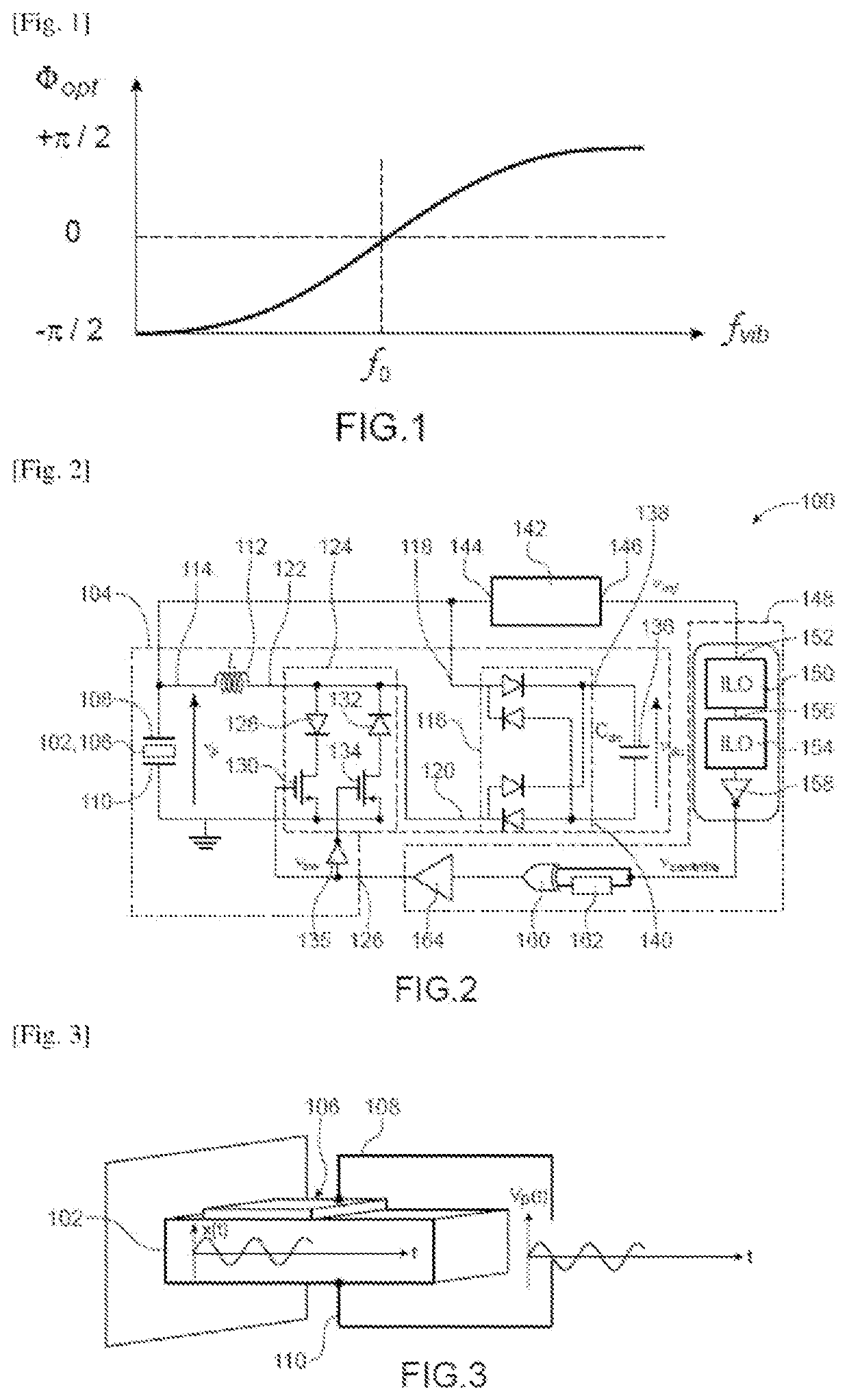
The patent describes a device that can automatically adjust the phase of a voltage or current generated by an electrical generator based on the frequency of mechanical excitation. This allows the generator to resonance with the vibration and maximize power transfer with very low consumption and almost instantaneous adjustment.

Problems solved by technology

However, as soon as the frequency of the vibrations deviates a little from the resonance frequency of the generator, the amplitude of the displacement decreases considerably, which reduces the amount of energy recovered.
These two devices strongly limit the integration of the system.
In addition, the placement of the accelerometer on the vibrating structure can be quite restrictive.
Although this technique is very efficient when the vibration frequency matches the resonance frequency of the piezoelectric generator, little energy is recovered when the piezoelectric generator is excited at frequencies different from its resonance frequency.
Thus, the slightest shift between the resonance frequency of the piezoelectric generator and the vibration frequency leads to drastic losses in performance.
However, none of the previously described solutions allows for automatic and fast control and adjustment of the value of the phase shift between the energy recovery instants and the resonator oscillations of the piezoelectric generator.

Method used


Image

  • Device for recovering or damping the vibratory energy of a resonant mechanical element
  • Device for recovering or damping the vibratory energy of a resonant mechanical element
  • Device for recovering or damping the vibratory energy of a resonant mechanical element

Examples


first embodiment

[0037]In a first embodiment, the electrical generator may further comprise:[0038]an electrical energy storage element including a first electrode electrically coupled to the first output electrode of the conversion element;[0039]an AC-to-DC voltage conversion device comprising a first input terminal electrically coupled to the first output electrode of the conversion element and a second input terminal electrically coupled to a second electrode of the electrical energy storage element; and[0040]a bi-directional switch configured to couple or not couple the second electrode of the electrical energy storage element to the second output electrode of the conversion element depending on the value of the signal received on the control input of the electrical generator.

[0041]According to a variant of the first embodiment, the electrical generator may comprise:[0042]an electrical energy storage element including a first electrode electrically coupled to the first output electrode of the con...

second embodiment

[0073]FIG. 12 schematically shows a device for recovering vibratory energy from a mechanical resonator ;

third embodiment

[0074]FIG. 13 schematically shows a device for recovering vibratory energy from a mechanical resonator ;

[0075]Identical, similar or equivalent parts of the various figures described below bear the same numerical references so as to facilitate the passage from one figure to another.

[0076]The various parts shown in the figures are not necessarily according to a uniform scale, to make the figures more readable.

[0077]The various possibilities (variants and embodiments) should be understood as not being exclusive of each other and may be combined with each other.


PUM


Abstract

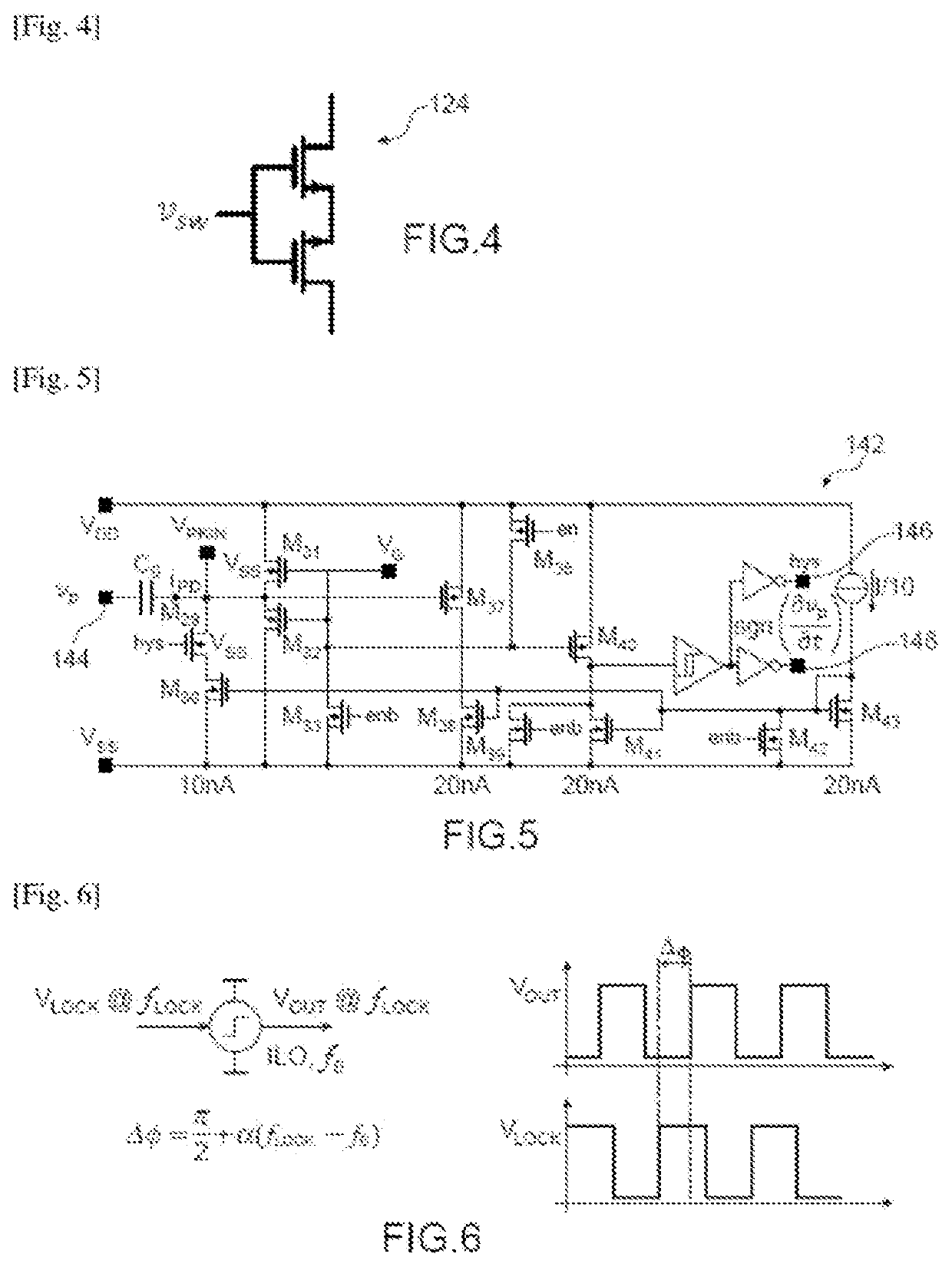
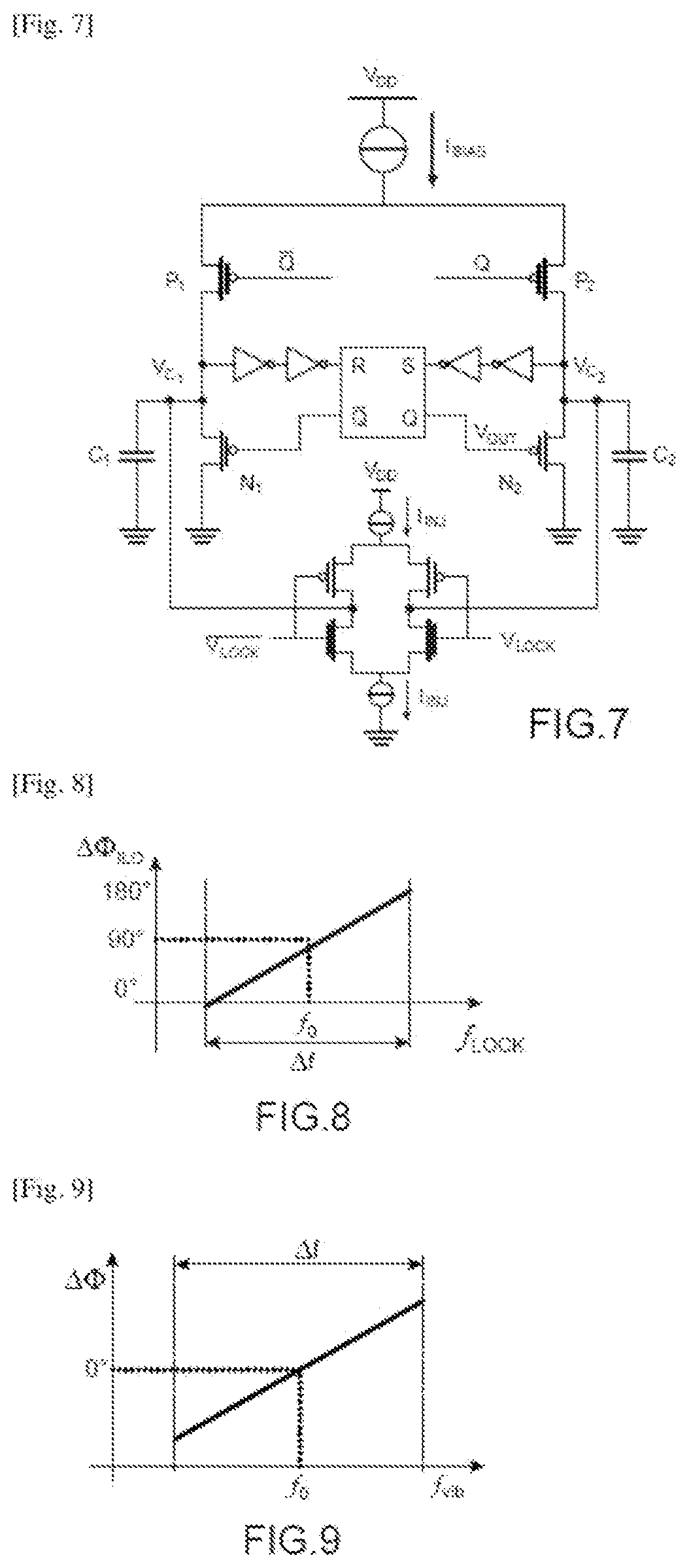
A device for recovering or dampening vibratory energy from a mechanical resonator, comprising:an electrical generator comprising an element for converting mechanical vibration energy into electrical charges coupled to the resonator, the electrical generator periodically transferring a portion of the electrical charges from one terminal of the conversion element to the other;a frequency variation to phase variation conversion device, comprising an injection-locked oscillator of which the free-running oscillation frequency is equal to the resonance frequency of the resonator, and supplying to the electrical generator a control signal of frequency equal to that of the signal outputted by the conversion element and of which the phase shift depends on the difference between the frequency of the signal outputted by the conversion element and the resonance frequency of the resonator.

Description

TECHNICAL FIELD[0001]The invention relates to the field of recovery or damping of the mechanical vibratory energy of a resonant mechanical element, or mechanical resonator. The invention can be applied in particular to the following fields:[0002]medical, such as for pacemakers;[0003]industrial maintenance, for example for the vibrations of production machines;[0004]sports, for example for the vibrations of shoe soles;[0005]automobile and aeronautical, for example for engine vibrations, fuselage vibrations, etc.[0006]real estate, for example for vibrations of structures such as bridges, buildings, etc.STATE OF THE PRIOR ART[0007]It is known to use a piezoelectric material to recover mechanical energy and convert it into storable electrical energy, for example, in a capacitor or battery. For this purpose, the piezoelectric material is, for example, placed at locations where significant mechanical deformations may occur: shoe soles, shoulder straps of a backpack, etc.[0008]In many appl...

Claims


Application Information

Patent Timeline
IPC IPC(8): H02N2/18H02M7/219
CPCH02N2/181H02N2/188H02M7/219H02K35/00
Inventor MOREL, ADRIENBADEL, ADRIENBADETS, FRANCKGOUX, NICOLASPILLONNET, GAËL
Owner COMMISSARIAT A LENERGIE ATOMIQUE ET AUX ENERGIES ALTERNATIVES
Learn More