Analog current limit adjustment for linear and switching regulators

a technology of analog current limit and switching regulator, which is applied in the direction of electric variable regulation, power conversion systems, instruments, etc., can solve the problems of imposing a current limitation on the pmu, reducing the input voltage of the pmu, and reducing the input voltage. the effect of automatic interruption of input power flow

Active Publication Date: 2013-10-22
DIALOG SEMICONDUCTOR GMBH
View PDF11 Cites 0 Cited by
  • Summary
  • Abstract
  • Description
  • Claims
  • Application Information

AI Technical Summary

Benefits of technology

[0017]A principal object of the present invention is to achieve a power management unit avoiding undesired automatic interruption of input power flow.
[0019]A further object of the present invention is to achieve a power management unit maximizing the power transferred from the power management unit to a system load (including a battery in case of battery operated systems).

Problems solved by technology

Strong input currents of DC-to-DC converters can cause a substantial voltage drop across this internal resistance.
This is generally done imposing a current limitation on the PMU according to the kind of power source connected to it.
Even respecting this limitation, an excessive length of the connection cable or a low quality power source can lead the PMU input voltage to fall below a lower threshold specified by the specific power source.
Subsequently without voltage drop the input voltage increases, an input voltage is admitted again and the input of the DC-to-DC converter starts to toggle, which is not acceptable.
The behavior of an architecture shown in FIG. 1 prior art is not robust: even a load current below the current limit can interrupt the power flow and cause start-up or operation failures.
When the average value of voltage pulses exceeds a reference voltage, the value of bias voltage is limited for establishing the maximum width of voltage pulses and duty cycle of the converter, and thereby limit the maximum line current drawn by the power supply.

Method used


Image

  • Analog current limit adjustment for linear and switching regulators
  • Analog current limit adjustment for linear and switching regulators
  • Analog current limit adjustment for linear and switching regulators

Examples


Embodiment Construction

[0028]The preferred embodiments disclose methods and systems to achieve a power management unit, i.e. transferring power from a power source to a system / battery) even in presence of power sources having low quality and high output resistance and / or high resistive cables. The present invention is applicable to switched DC-to-DC converters as well as to linear converters such as e.g. low drop-out (LDO) converters.

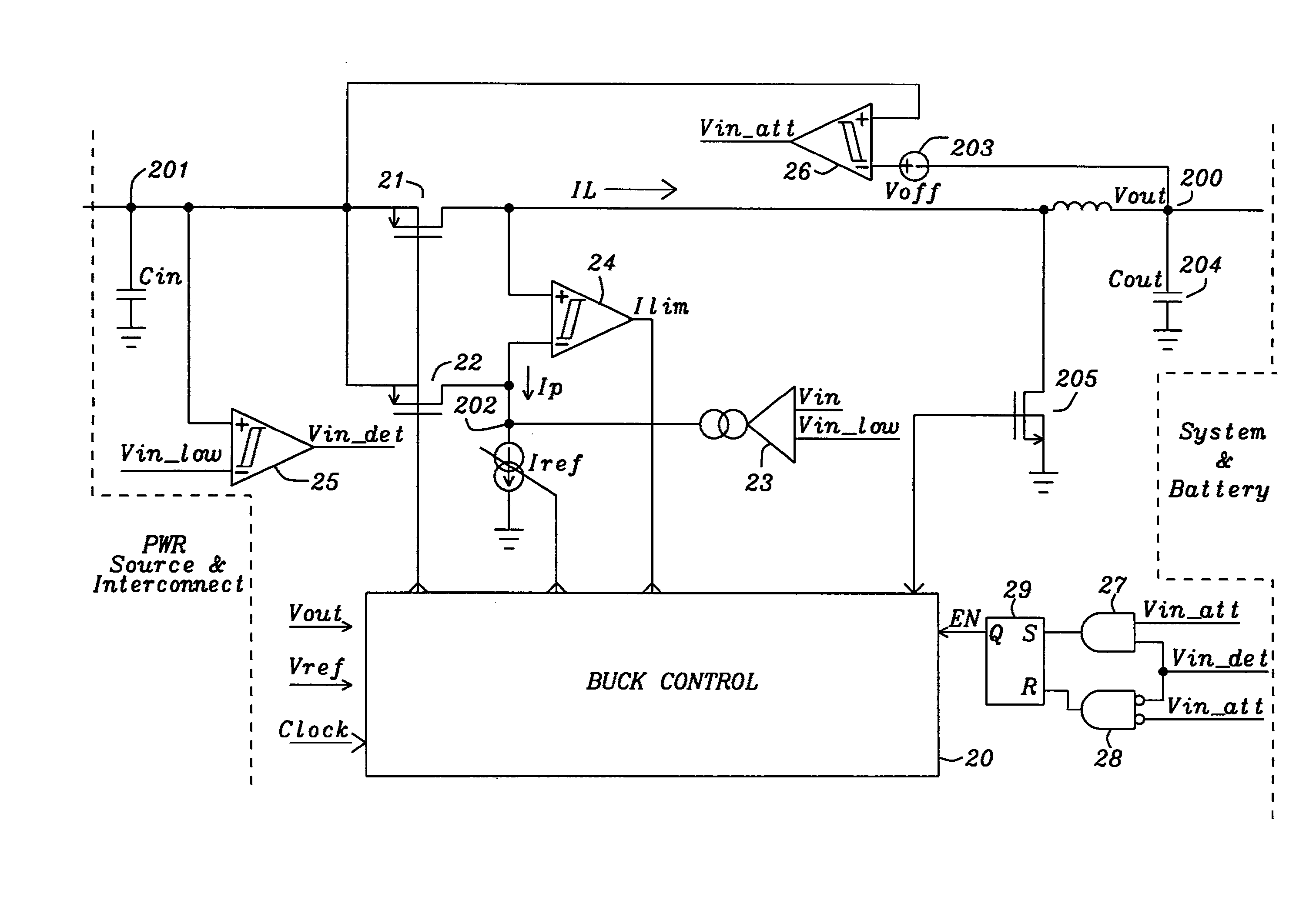
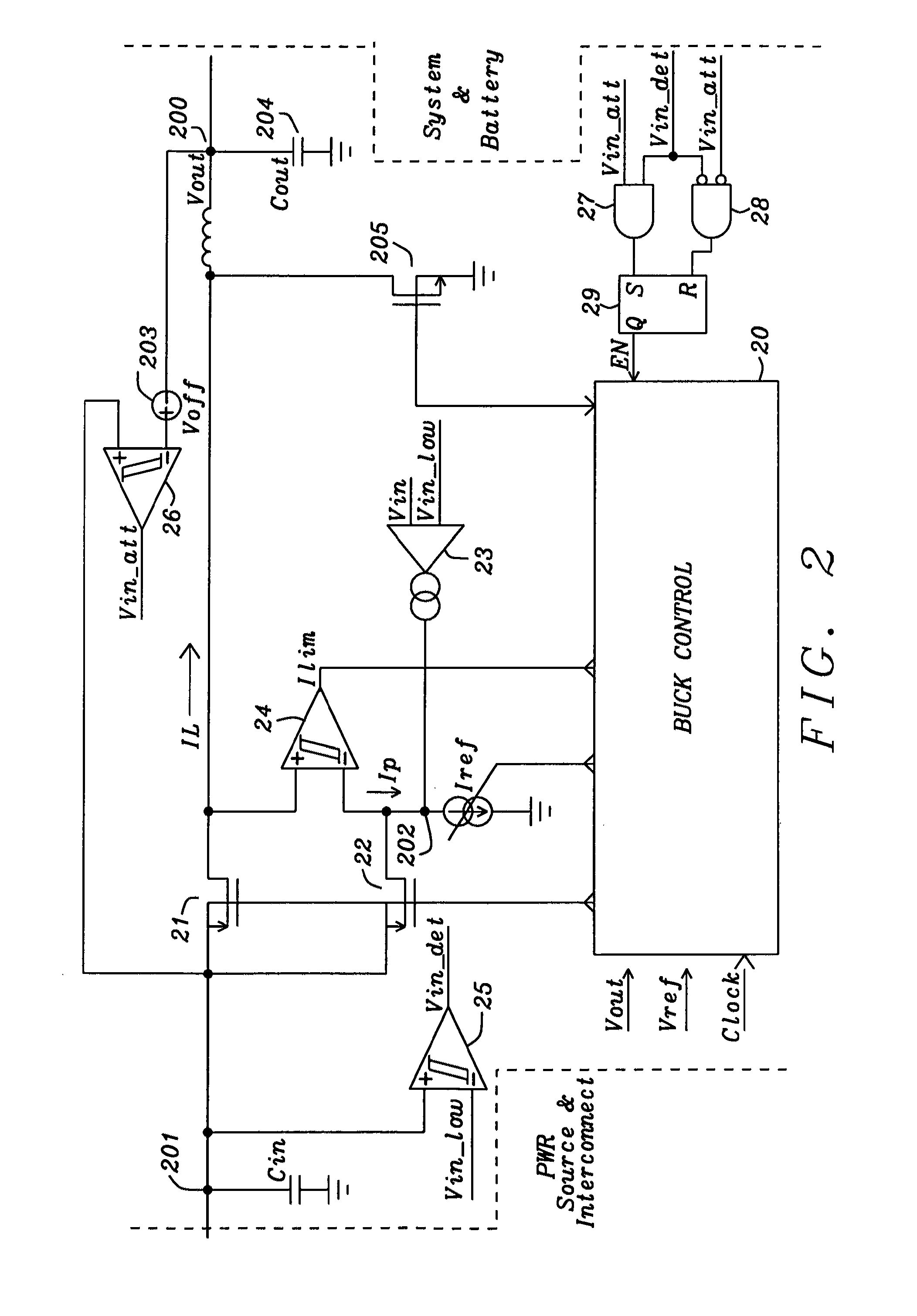
[0029]The dynamic current limit control scheme of the present invention is depicted in FIG. 2. FIG. 2 shows a power path of a power management unit. In a preferred embodiment of the invention a current limited buck voltage regulator is used for converting DC / DC power but this is not limiting the scope of the present invention, which would be applicable also to a linear regulator as e.g. an LDO.

[0030]The output port 200 is connected to a system and / or a battery; the input port 201 is connected to a power source via an interconnection.

[0031]The buck converter shown limits a cur...


PUM


Abstract

Circuits and methods for dynamic adjustment of the current limit of a power management unit to avoid unwanted automatic interruption of the power flow have been disclosed. The invention can be applied to switched and linear DC-to-DC converters. The power management unit is automatically adjusted to the output resistance of a power source (including interconnect resistance). The invention maximizes the time and hence the power transferred from a power management unit to the system (including the battery, in case of battery operated systems). The input current is reduced, thus increasing the input voltage in case of a high voltage drop across the internal resistance including interconnections between power source and power management unit.

Description

RELATED APPLICATIONS[0001]This application is related to the following US patent application:[0002]DS08-009B, titled “Automatic Current Limit Adjustment for linear and switching Regulators”, Ser. No. 12 / 800,846, filing date May 24, 2010,and the above application is herein incorporated by reference in their entirety.BACKGROUND OF THE INVENTION[0003](1) Field of the Invention[0004]This invention relates generally to the field of DC-to-DC converters and relates more specifically to linear and switched DC-to-DC converters having a dynamic automatic input current limit control.[0005](2) Description of the Prior Art[0006]DC-to-DC converters receive usually DC power from a source comprising a voltage source and an internal resistance. The resistance of a power source, comprising internal resistance and external resistance including the resistance of cables, is often unknown and may often not be neglected. Strong input currents of DC-to-DC converters can cause a substantial voltage drop acr...

Claims


Application Information

Patent Timeline
Patent Type & Authority Patents(United States)
IPC IPC(8): G05F5/00G05F1/565
CPCH02M3/156
Inventor SCALDAFERRI, STEFANOWOLF, CHRISTIANMARSCHALKOWSKI, ERIC
Owner DIALOG SEMICONDUCTOR GMBH
Why Eureka
Try Eureka