Installation of fiber-to-the-premise using optical demarcation devices

a technology of optical demarcation device and installation method, which is applied in the direction of optics, optical elements, instruments, etc., can solve the problems of affecting the adoption rate of fttp communication services, detection and location of fiber,

Active Publication Date: 2013-11-19
GOOGLE LLC
View PDF29 Cites 21 Cited by
  • Summary
  • Abstract
  • Description
  • Claims
  • Application Information

AI Technical Summary

Problems solved by technology

However, ongoing operation and maintenance expenses associated with the fiber plant also impact the adoption rate of FTTP communication services.
One such expense is the detection and location of fiber faults (e.g., a fiber cut or breakage) that interrupt communication services.

Method used


Image

  • Installation of fiber-to-the-premise using optical demarcation devices
  • Installation of fiber-to-the-premise using optical demarcation devices
  • Installation of fiber-to-the-premise using optical demarcation devices

Examples


Embodiment Construction

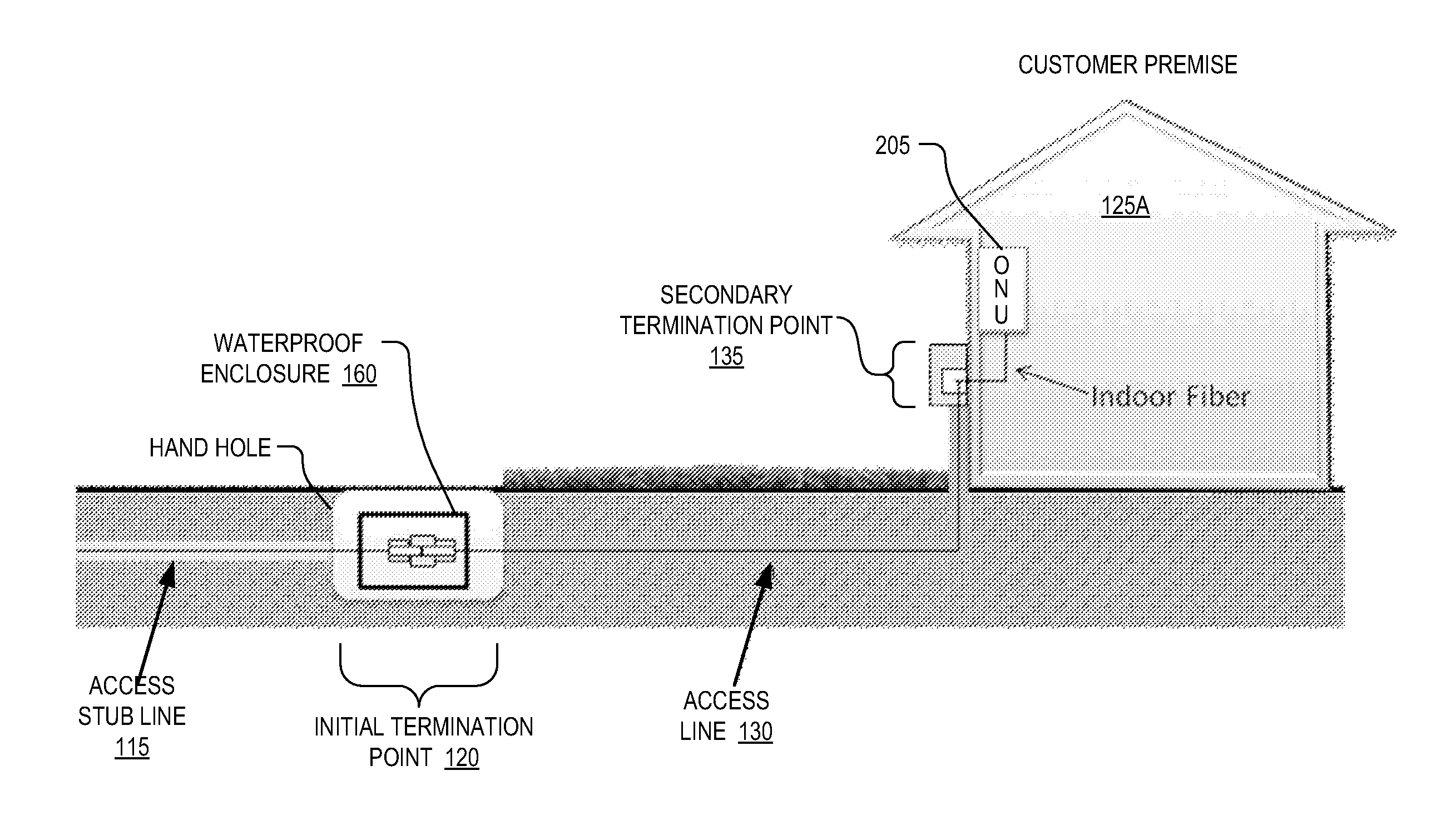
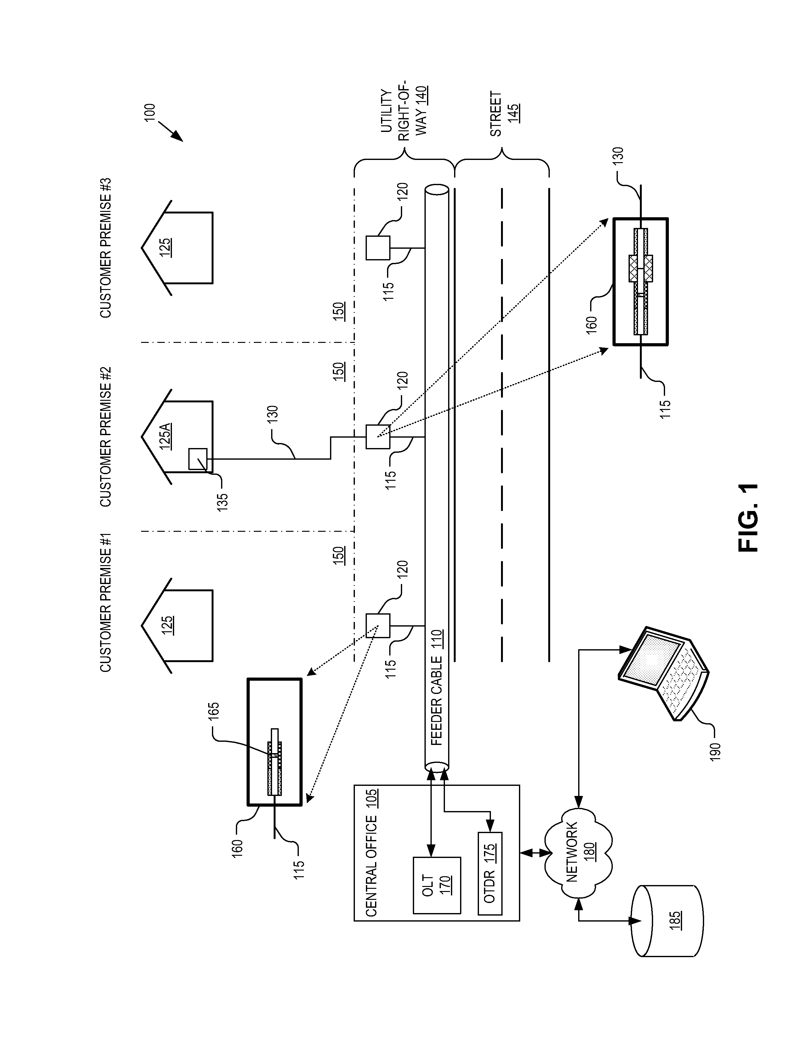
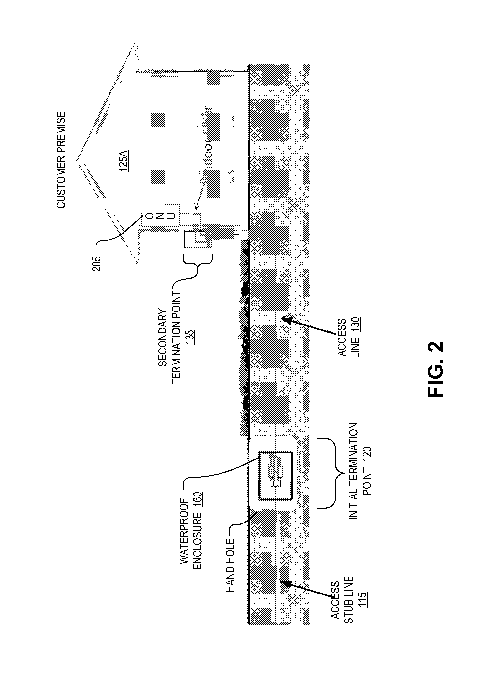
[0010]Embodiments of a system, apparatus and method for installing a fiber optic network are described herein. In the following description numerous specific details are set forth to provide a thorough understanding of the embodiments. One skilled in the relevant art will recognize, however, that the techniques described herein can be practiced without one or more of the specific details, or with other methods, components, materials, etc. In other instances, well-known structures, materials, or operations are not shown or described in detail to avoid obscuring certain aspects.

[0011]Reference throughout this specification to “one embodiment” or “an embodiment” means that a particular feature, structure, or characteristic described in connection with the embodiment is included in at least one embodiment of the present invention. Thus, the appearances of the phrases “in one embodiment” or “in an embodiment” in various places throughout this specification are not necessarily all referri...


PUM


Abstract

A technique for installing a fiber optic network includes preparing a physical site to install a feeder cable and a plurality of access stub lines along a plurality of customer premises that potentially may connect to the feeder cable to obtain communication services. Each of the access stub lines extends from the feeder cable towards a customer premise and each ends at a different initial termination point. There is a one-to-one correspondence between the customer premises and the access stub lines extending from the feeder cable. A demarcation device is attached to an end of each of the access stub lines at each of the initial termination points. The demarcation device includes an optical reflector that is reflective to an optical test signal for testing integrity of the feeder cable and an associated one of the access stub lines.

Description

TECHNICAL FIELD[0001]This disclosure relates generally to fiber optic networks, and in particular but not exclusively, relates to the installation and build out of fiber optic networks.BACKGROUND INFORMATION[0002]Fiber networks can be used to transport light that is modulated to carry information and to deliver communication services in various configurations, including broadband fiber-to-the-premise (“FTTP”) communication services. In order to promote widespread deployment of FTTP broadband infrastructure, it is desirable to reduce the cost of fiber plant construction, which consists of as much as 80% of the total cost for FTTP deployments and is dominated by labor costs in developed countries. Techniques that can reduce this upfront expense associated with the initial fiber plant can further this goal. However, ongoing operation and maintenance expenses associated with the fiber plant also impact the adoption rate of FTTP communication services. One such expense is the detection a...

Claims


Application Information

Patent Timeline
Patent Type & Authority Patents(United States)
IPC IPC(8): G02B6/00
CPCG02B6/3825H04B10/071H04B10/272G02B6/4451G02B6/4466G02B6/3845G02B6/501G02B6/475
Inventor LAM, CEDRIC F.KELLY, JAMES F.
Owner GOOGLE LLC
Why Eureka
Try Eureka