
Power management scheme for portable data collection devices utilizing location and position sensors

a technology for positioning and position sensors and data collection devices, applied in power management, high-level techniques, instruments, etc., can solve the problems of poor energy consumption management efficiency of time-based systems, difficult to optimize power management to maximize the available energy budget of portable data terminals, and difficult to manage energy consumption

Active Publication Date: 2013-11-19
HAND HELD PRODS
View PDF16 Cites 765 Cited by
  • Summary
  • Abstract
  • Description
  • Claims
  • Application Information

AI Technical Summary

Benefits of technology

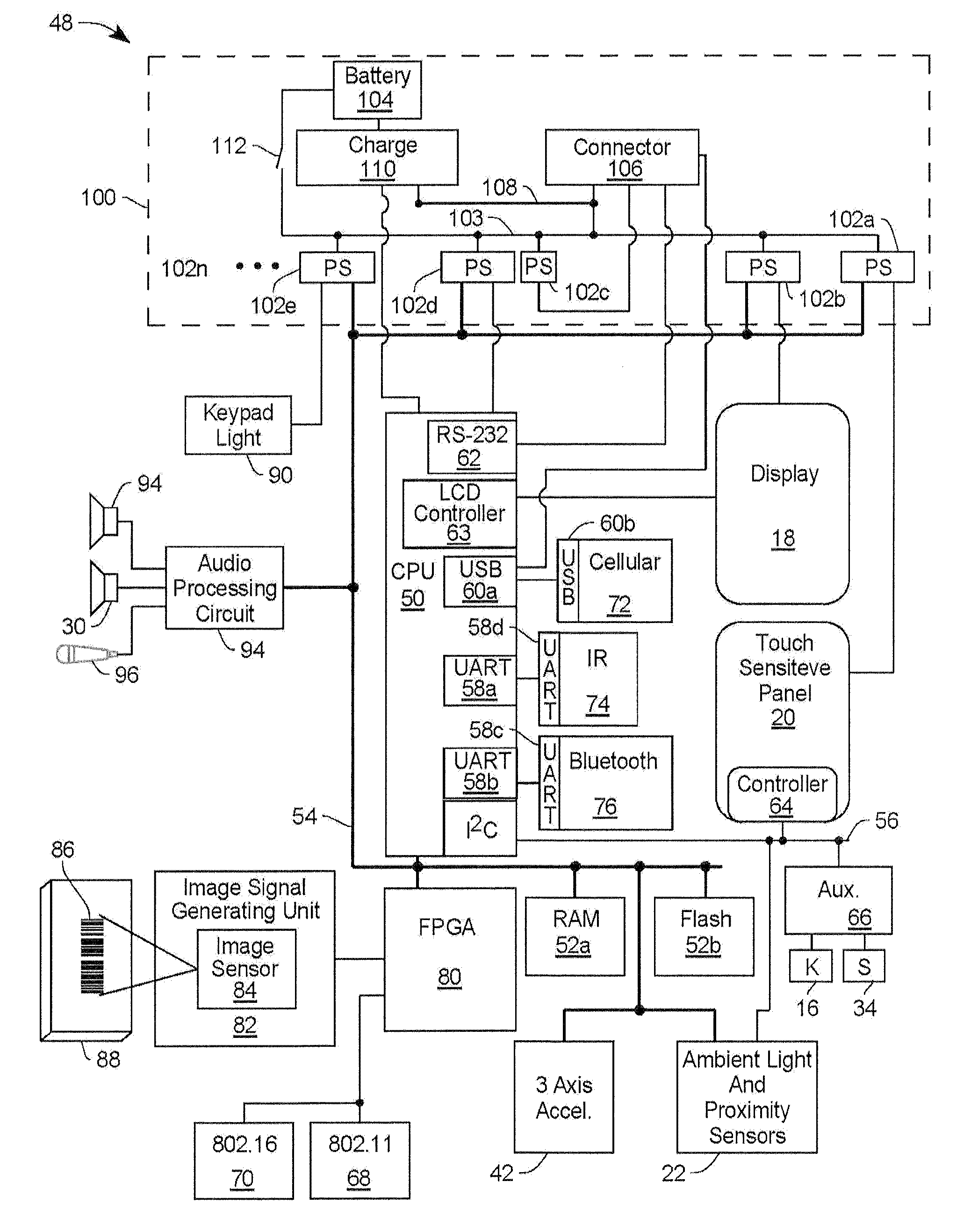
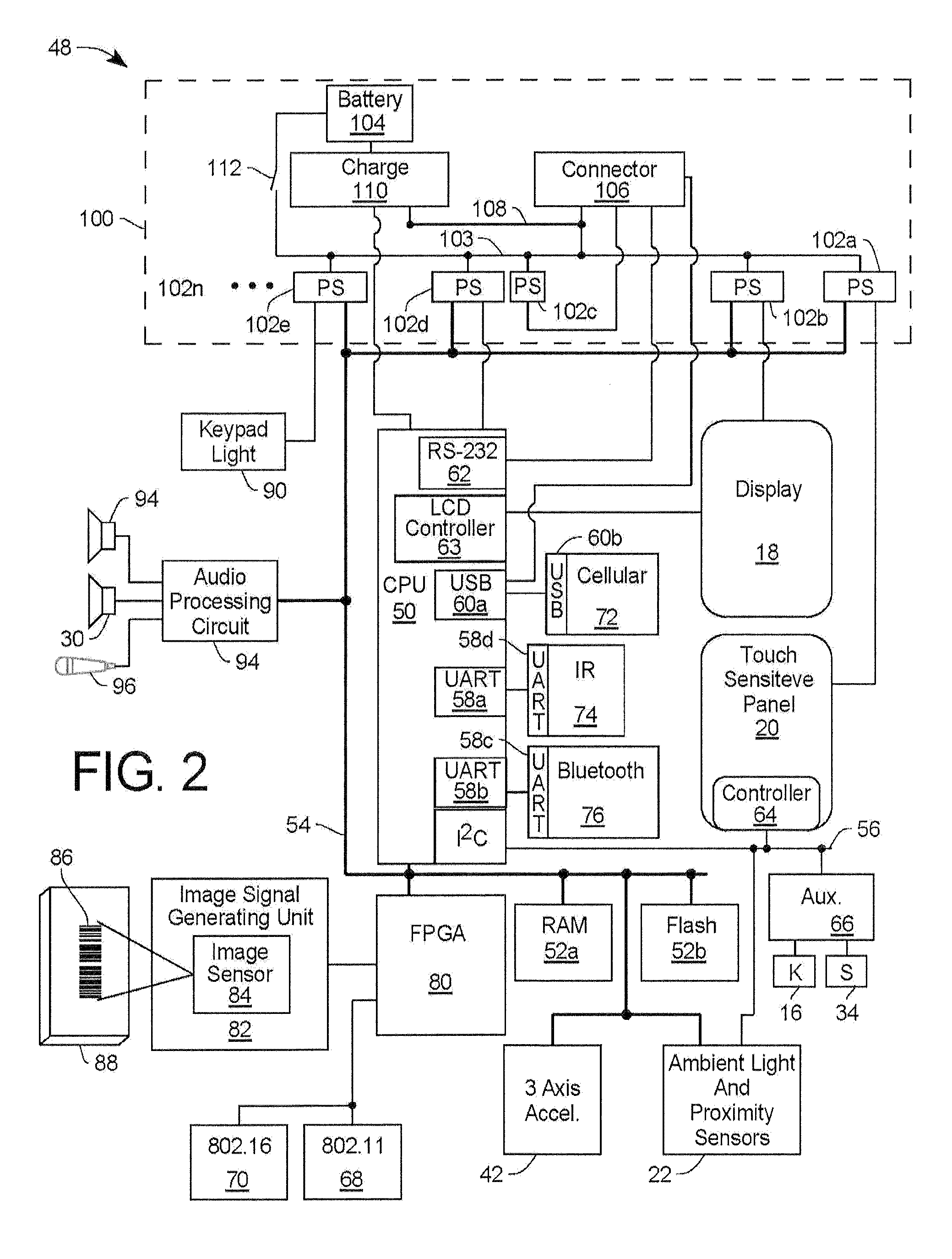
The patent is about a device called a data collection device (DCD) that can manage remote devices like portable data terminals (PDTs) to conserve power and track performance issues. The DCD has a display and a keypad for selecting options and a touch-sensitive panel for selecting options. It also has sensors for detecting ambient light and proximity, and a built-in bar code scanner. The DCD can be connected to a computer network to manage the remote devices. The technical effects of the patent are an improved interface for managing remote devices and optimizing power management.

Problems solved by technology

Optimizing power management to maximize the available energy budget in portable data terminal is a constant struggle.
Due to an increased peripheral set, ruggedized portable data terminals are particularly problematic with respect to power management issues.
However, time based systems are much less efficient at managing energy consumption.
However, some RDM systems accumulate vast amounts of diagnostic and performance data.
Organizing the data in a clear, concise, meaningful, and intuitive way on the graphical user interface of a computer display is a problem.
Either too much data is presented so as to be cluttered and confusing, or the user has to navigate through multiple, sometimes non-intuitive, dialogs to access desired information.

Method used


Image

  • Power management scheme for portable data collection devices utilizing location and position sensors
  • Power management scheme for portable data collection devices utilizing location and position sensors
  • Power management scheme for portable data collection devices utilizing location and position sensors

Examples


Embodiment Construction

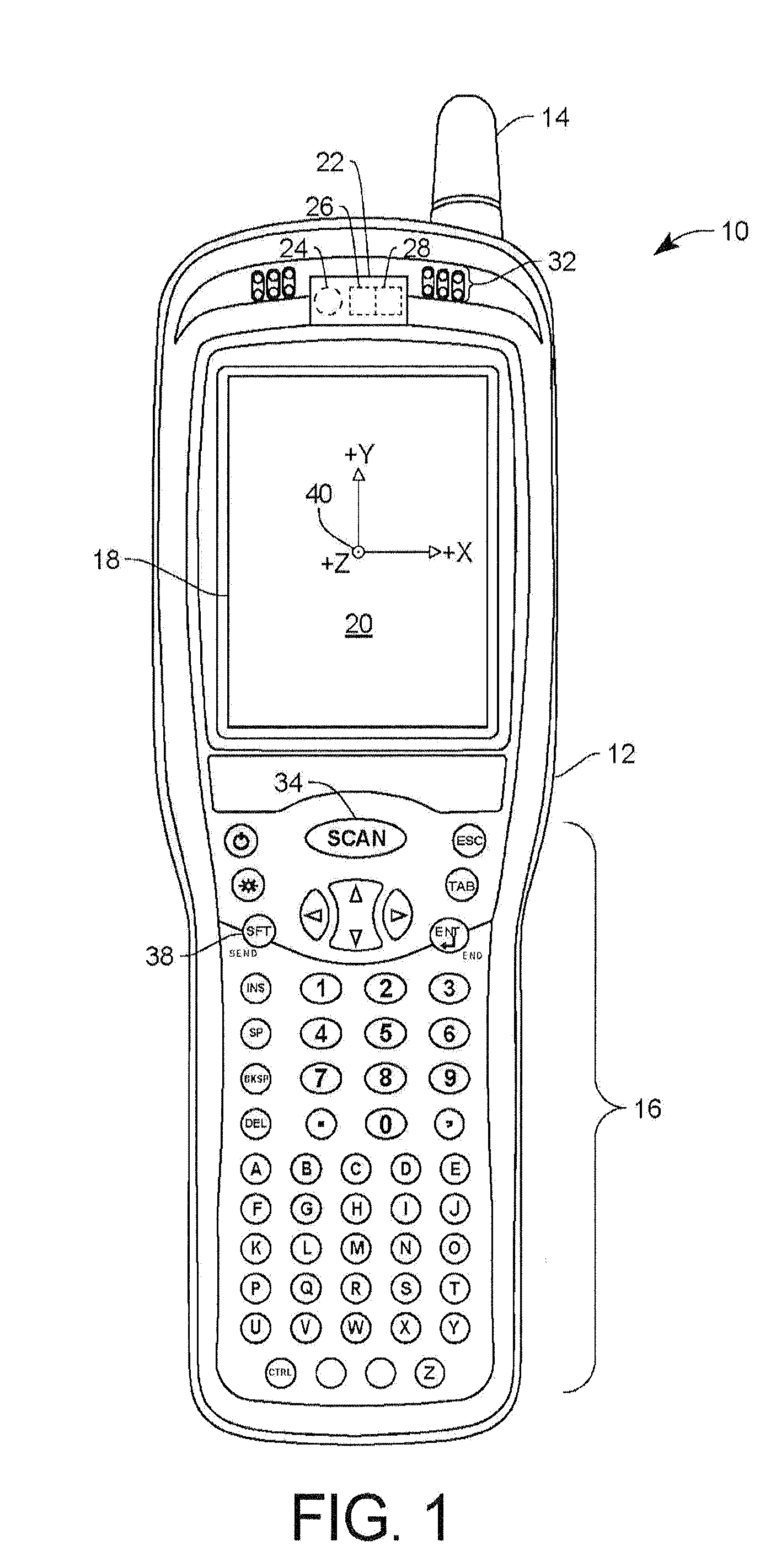
[0013]Turning now to the drawings, FIG. 1 shows a data collection device (DCD) 10, which may be a Personal Digital Assistant (PDA), according to one embodiment of the present invention. The DCD 10 has a main body 12 with an antenna 14 attached to the main body 12. A keypad 16 is located in the lower portion of the DCD 10, and a display 18 is located in an upper portion of the DCD 10. A touch sensitive panel 20 is superimposed on the display 18 for allowing a user to select options on the display directly.

[0014]Located above the display 18 is a combination ambient light sensor and proximity sensor 22, which may include a LED 24, a combination photodiode array and optical filter 26 to detect the amount of ambient light in the wavelengths detected by the human eye, and a second combination photodiode array and optical filter 28 to detect the amount of light in the infrared range which is used for proximity detection. Located slightly above and to the right of the combination ambient li...


PUM


Abstract

A data collection device (DCD) is placed in a first low power mode after the DCD has been in a first predetermined position, and placed in a second low power mode after a first predetermined period of time. In another embodiment the DCD includes a wireless telephone, and a proximity sensor which detects when the DCD is close to a user's face, wherein the telephone is automatically put in a handset mode when the DCD is close to a user's face, and automatically put in a speakerphone mode when the DCD is not close to a user's face.

Description

FIELD OF THE INVENTION[0001]This invention relates to the management of remote devices such as portable data terminals (PDTs), and more particularly to an interface for managing the remote devices.BACKGROUND OF THE INVENTION[0002]Optimizing power management to maximize the available energy budget in portable data terminal is a constant struggle. Due to an increased peripheral set, ruggedized portable data terminals are particularly problematic with respect to power management issues. It is desirable to put the portable data terminal into a low power state whenever the operator is not actively using the device. Many systems implement time based inactivity determination. However, time based systems are much less efficient at managing energy consumption.[0003]The remote devices can have the ability to have there configuration changed or to have a new application program installed while away from the central office. U.S. Patent Publication No. 2009 / 0044003 A1 to Berthiaume et al. teache...

Claims


Application Information

Patent Timeline
Patent Type & Authority Patents(United States)
IPC IPC(8): H04B1/38H04M1/72454
CPCH04W52/0254G06F1/3203H04W4/026H04W52/027H04W4/023H04W52/0274Y02D30/70H04M1/72454
Inventor SAUERWEIN, JR., JAMES T.HINSON, DOUGLAS M.
Owner HAND HELD PRODS
Learn More