Surface light source device and display device

a light source device and surface technology, applied in the direction of lighting and heating apparatus, planar/plate-like light guides, instruments, etc., can solve the problems of increased components, limited welding and bonding properties of the material supporting, and diffuse reflection, so as to achieve easy assembly

Active Publication Date: 2013-11-26
TRIVALE TECH
View PDF6 Cites 0 Cited by
  • Summary
  • Abstract
  • Description
  • Claims
  • Application Information

AI Technical Summary

Benefits of technology

[0008]An object of the present invention is to provide a surface light source device that is easily assembled, supports and fixes point light sources and a light guide plate so as not to become misaligned without increasing the number of components, and is capable of causing light beams emitted from the point light sources to be incident on the light guide plate with efficiency.
[0012]Even in a case where the light guide plate is deformed, for example, is warped, the position of the point light source with respect to the incidence surface is fixed by disposing the point light source to abut against the projection of the light guide plate. Accordingly, there is no reduction in efficiency with which the light beam emitted from the point light source is incident on the incidence surface of the light guide plate. Further, a support or the like is not required separately, which makes the assembly easier.

Problems solved by technology

This causes drawbacks that an interface of a welding portion becomes uneven, leading to diffuse reflection of incident light beams, and that a material for the support is limited in terms of welding and bonding properties for the LED lamps.
Moreover, the drawback is that the support needs to be used for fixing the LEDs, which increases the number of components and makes the assembly more difficult.

Method used


Image

  • Surface light source device and display device
  • Surface light source device and display device
  • Surface light source device and display device

Examples


second preferred embodiment

[0047](Second Preferred Embodiment)

[0048]

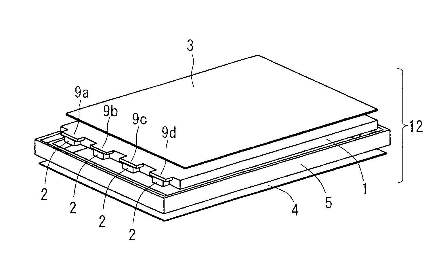
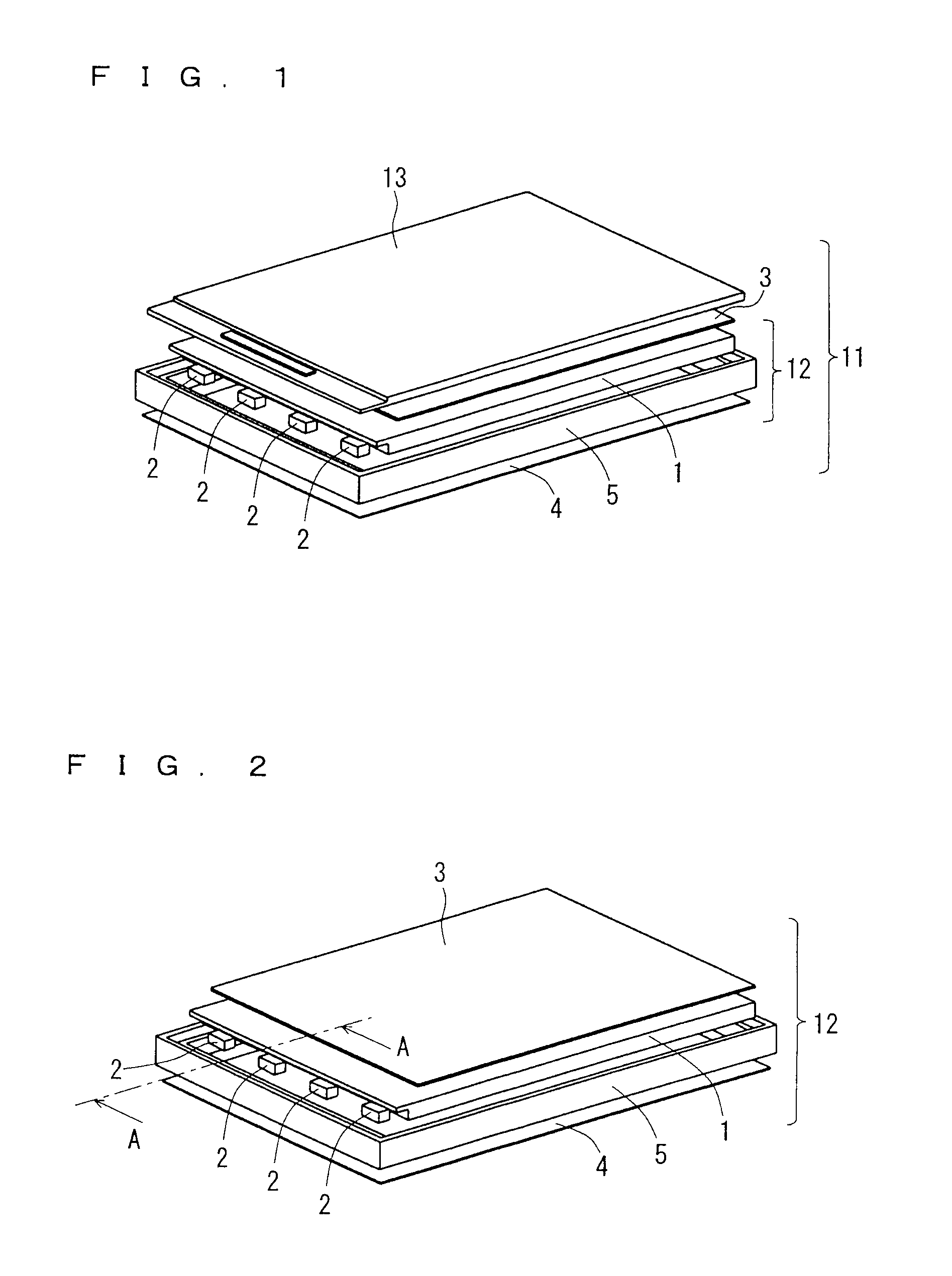
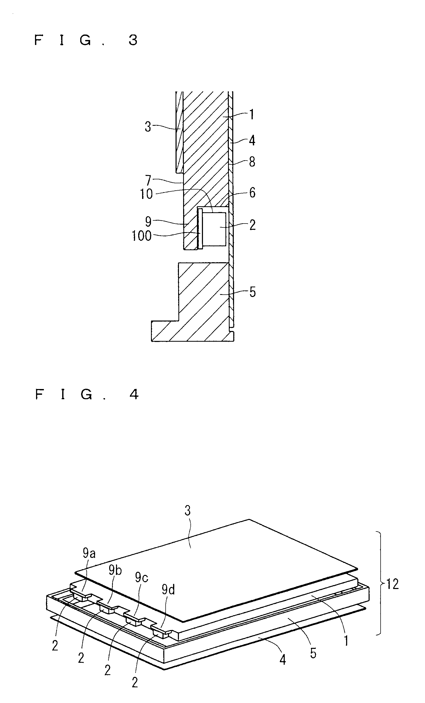
[0049]FIG. 5 is a perspective view showing the configuration of the display device 11 including the surface light source device 12 according to this preferred embodiment, and FIG. 6 is a perspective view showing the configuration of the surface light source device 12 according to this preferred embodiment. FIG. 7 is a partial cross-sectional view of the surface light source device 12, which is taken along the A-A direction of FIG. 6. While the eaves portion 9 is disposed such that the upper surface of the eaves portion 9 is flush with the exit surface 7 of the light guide plate 1 in the first preferred embodiment, in the second preferred embodiment, an eaves portion 90 is disposed in such a step manner as to be higher than the exit surface 7. The configuration other than the eaves portion 90 is similar to that of the first preferred embodiment, and thus description thereof is omitted.

[0050]The eaves portion 90 is provided outside the display ...


PUM


Abstract

Provided is a surface light source device including a light guide plate, and at least one point light source that is disposed to be adjacent to an incidence surface of the light guide plate and irradiates the incidence surface with a light beam. The light guide plate includes, at least at a position at which the point light source is disposed, at least one projection projecting from the incidence surface toward a direction in which the point light source is disposed.

Description

BACKGROUND OF THE INVENTION[0001]1. Field of the Invention[0002]The present invention relates to a surface light source device and a display device using the same.[0003]2. Description of the Background Art[0004]Surface light source devices, which irradiate a rear surface of a display element such as a liquid crystal panel with a light beam to illuminate a display screen from a back surface, include side light type and direct type ones. Light sources are arranged on side surfaces of a casing in the side light type (also referred to as edge light type) surface light source device, while a light source is arranged on a rear surface of a casing by being opposed to a liquid crystal panel in the direct type surface light source device.[0005]Further, the side light type surface light source devices include devices in which a light guide plate is used for guiding a light beam from a light source to an opening of a casing. In a surface light source device using a light guide plate, the light...

Claims


Application Information

Patent Timeline
Patent Type & Authority Patents(United States)
IPC IPC(8): F21V7/04
CPCG02B6/002G02B6/0091G02B6/0021
Inventor KIYOHARA, TORU
Owner TRIVALE TECH
Why Eureka
Try Eureka