
Rolling bearing

a bearing and rolling bearing technology, applied in the direction of bearings, roller bearings, shafts, etc., can solve the problems of affecting the material requirement and weight of the bearing ring, deteriorating the bearing ring bearing capacity, etc., to achieve the reduction of the design space of the transmission, the effect of reducing the weight and keeping the material requirement at a lower level

Inactive Publication Date: 2013-11-26
SCHAEFFLER TECH AG & CO KG
View PDF6 Cites 14 Cited by
  • Summary
  • Abstract
  • Description
  • Claims
  • Application Information

AI Technical Summary

Benefits of technology

This patent is about a new arrangement for a bearing that is used in power take-off gears of automotive vehicles. The new arrangement includes a lash compensation element, which helps to reduce the space needed for the bearing and makes the bearing stronger. The design of the bearing takes into account the space needed for other parts, so it can be made smaller and lighter while still being effective. The new arrangement also has one or more radial projections that keep the lash compensation element securely in place during operation. Overall, the new arrangement allows for a more efficient and reliable bearing design.

Problems solved by technology

If an insufficient quantity of material remains behind in the regions next to the raceways of the rolling elements for supporting the rolling contact of the rolling elements with the raceways, the bearing capacity of the bearing ring is deteriorated.
Moreover, for being able to receive the TCE's, the bearing rings must have generous radial and axial dimensions, and this has a detrimental effect on their material requirement and their weight.

Method used


Image

  • Rolling bearing
  • Rolling bearing
  • Rolling bearing

Examples


Embodiment Construction

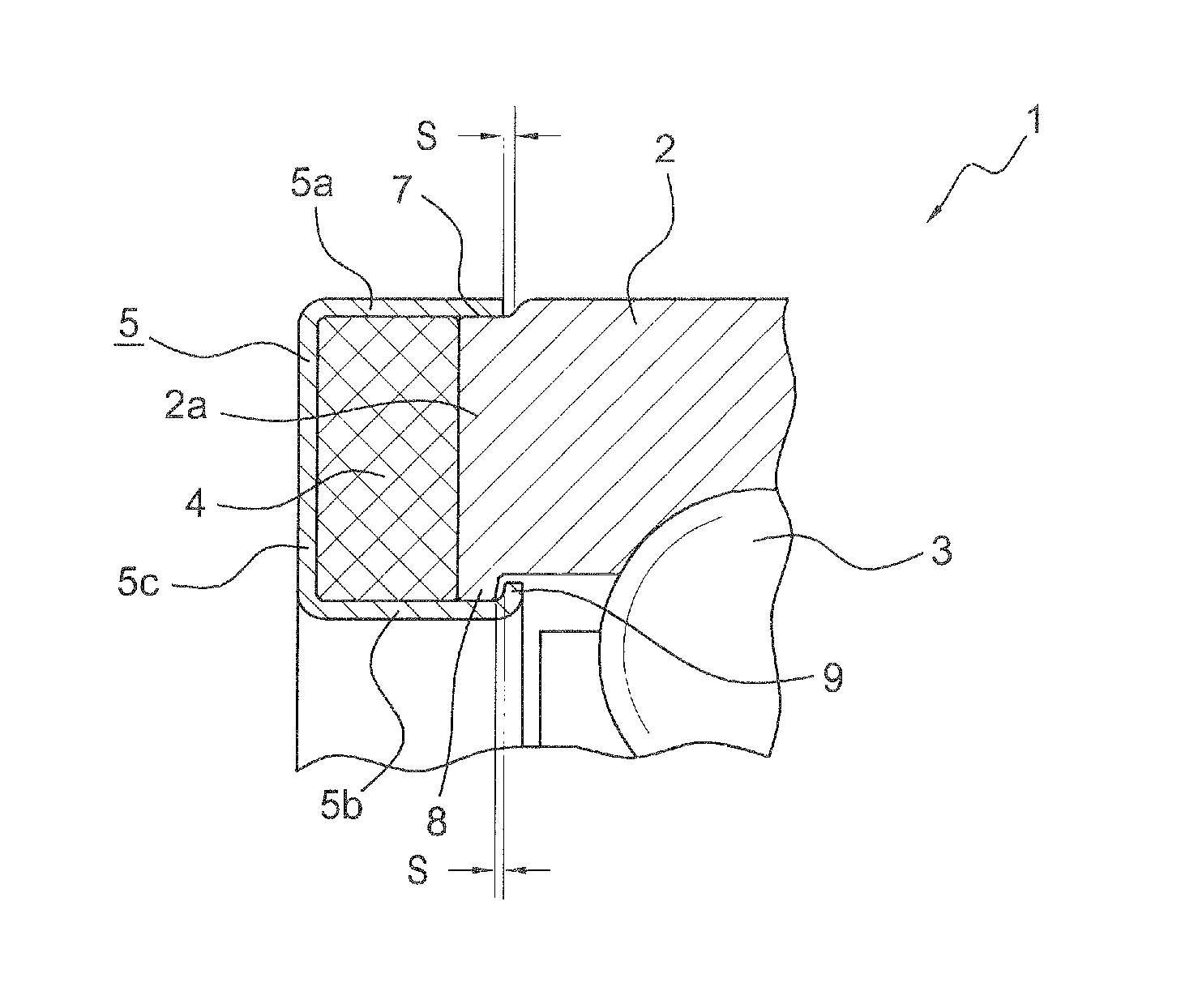
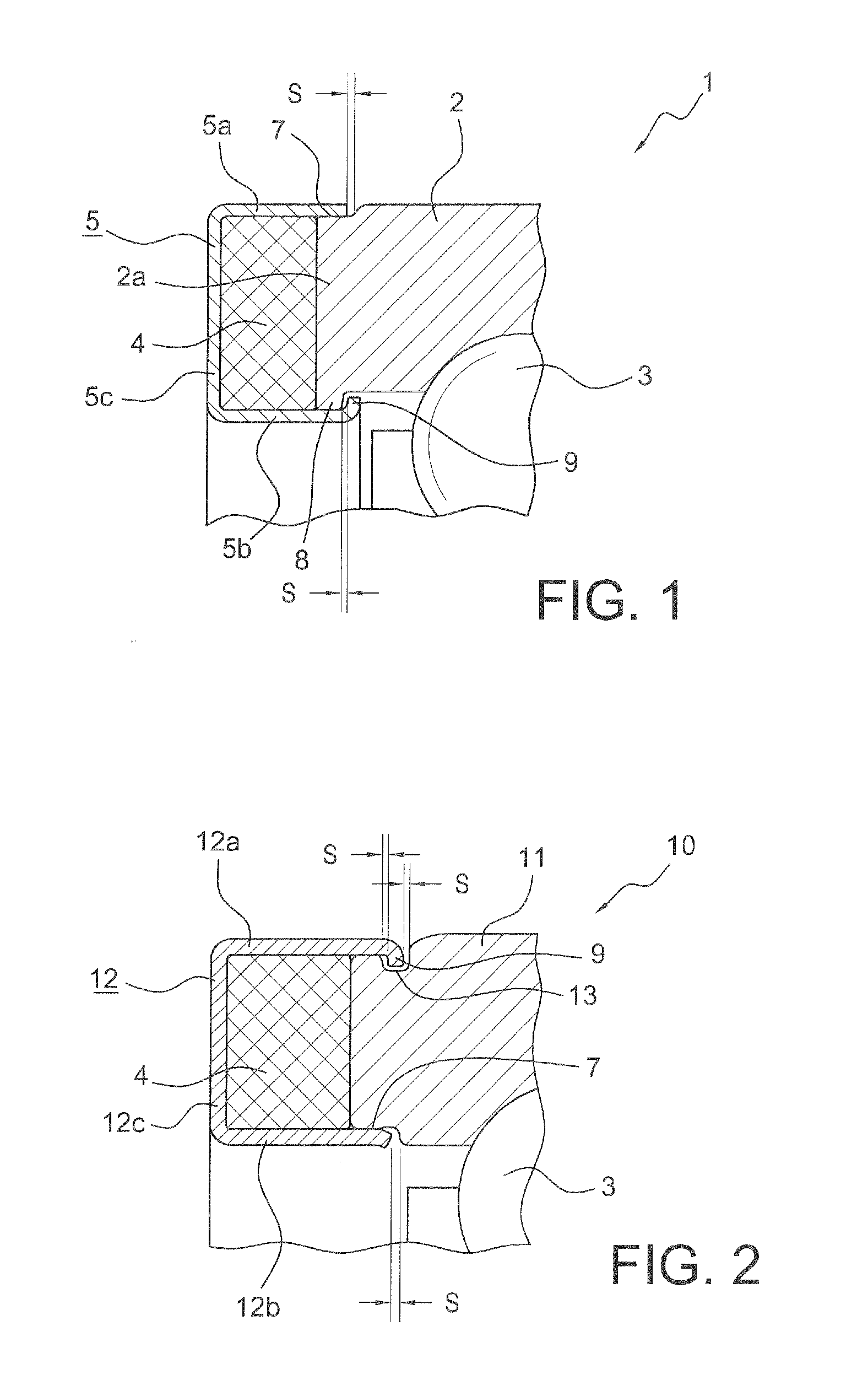
[0034]FIG. 1 shows a detail of a longitudinal section through a rolling bearing 1. The rolling bearing 1 comprises at least one bearing ring 2, rolling elements 3 in the form of balls and a lash compensation element 4 possessing temperature-dependent extendably. The bearing ring 2 in this case an outer bearing ring of the rolling hearing but, alternatively, the bearing ring can also be an inner bearing ring of a rolling hearing. The lash compensation element 4 is surrounded by an angular ring profile 5. The ring profile comprises two legs 5a and 5b directed axially parallel to the axis of rotation of the rolling bearing 1. The legs 5a and 5b have a hollow cylindrical configuration and are connected to each other in radial directions by a cross-connection 5c in the form of an annular disk.

[0035]The bearing ring 2 comprises, on an outer side, a radial depression 7 that forms an inner corner so that the diameter of the bearing ring 2 is reduced in a step shape radially on the outer sid...


PUM


Abstract

A rolling bearing which has at least one lash compensation element possessing temperature-dependent extendably arranged on one bearing ring of the rolling bearing. The lash compensation element is surrounded at least partially by an angular ring profile. The angular ring profile has at least one leg directed axially parallel to an axis of rotation of the angular contact roller bearing. The ring profile is retained by the leg by positive axial engagement for limited axial movement on the bearing ring such that the lash compensation element is supported by the ring profile by positive engagement so as to be radially immovable on the bearing ring while being guided for axial movement on the bearing ring.

Description

CROSS-REFERENCE TO RELATED APPLICATION[0001]This application claims the priority of U.S. 61 / 407,132 filed on Oct. 27, 2010, which is incorporated herein by reference.FIELD OF THE INVENTION[0002]The invention concerns a rolling bearing comprising at least one lash compensation element possessing temperature-dependent extendably arranged on one bearing ring of the rolling bearing. The lash compensation element is surrounded at least partially by an angular ring profile.BACKGROUND OF THE INVENTION[0003]Among rolling bearings, radial rolling bearings, thrust rolling bearings and angular contact rolling bearings are used for the mounting of shafts and other rotatable machine components, preferably in vehicle transmissions. The generic rolling bearings comprise at least one row or a plurality of rows of rolling elements that are supported on rolling contact raceways. The rolling elements are balls and rollers. Rollers of smaller diameter with a certain length are also called needle roller...

Claims


Application Information

Patent Timeline
Patent Type & Authority Patents(United States)
IPC IPC(8): F16C19/24F16C25/08
CPCF16C25/08F16C2202/22F16C2361/61
Inventor INCE, MARION JACKZHONG, GUIHUI
Owner SCHAEFFLER TECH AG & CO KG
Learn More