Analysis device

a technology of an analysis device and a reagent, which is applied in the direction of instruments, material electrochemical variables, laboratory glassware, etc., can solve the problems of unsatisfactory solutions of reagent feeding, and achieve the effect of efficient heat transfer and very rapid setting

Active Publication Date: 2013-12-03
BOEHRINGER LNGELHEIM VETMEDICA GMBH
View PDF17 Cites 13 Cited by
  • Summary
  • Abstract
  • Description
  • Claims
  • Application Information

AI Technical Summary

Benefits of technology

[0019]In the case of the chip card module, the silicon chip is advantageously mounted on a gold-coated copper layer only approximately 50 μm thick. This is the middle metal zone of known chip card modules, which is not used for electrical contacting points in the card reader. This free zone can consequently be used in the card reader, which acts here equally as an evaluation device, for directly contacting a cooling element, for example a Peltier cooler, to the corresponding location of the chip card module. On account of the placement (50 μm thick metallic contact with respect to the chip), an efficient heat transfer is consequently possible, so that a defined temperature can be set very quickly, in particular also by cooling.

Problems solved by technology

The problems of feeding in reagents are not satisfactorily solved in the prior art.

Method used


Image

  • Analysis device
  • Analysis device
  • Analysis device

Examples


Embodiment Construction

[0026]Reference will now be made in detail to the preferred embodiments of the present invention, examples of which are illustrated in the accompanying drawings, wherein like reference numerals refer to like elements throughout.

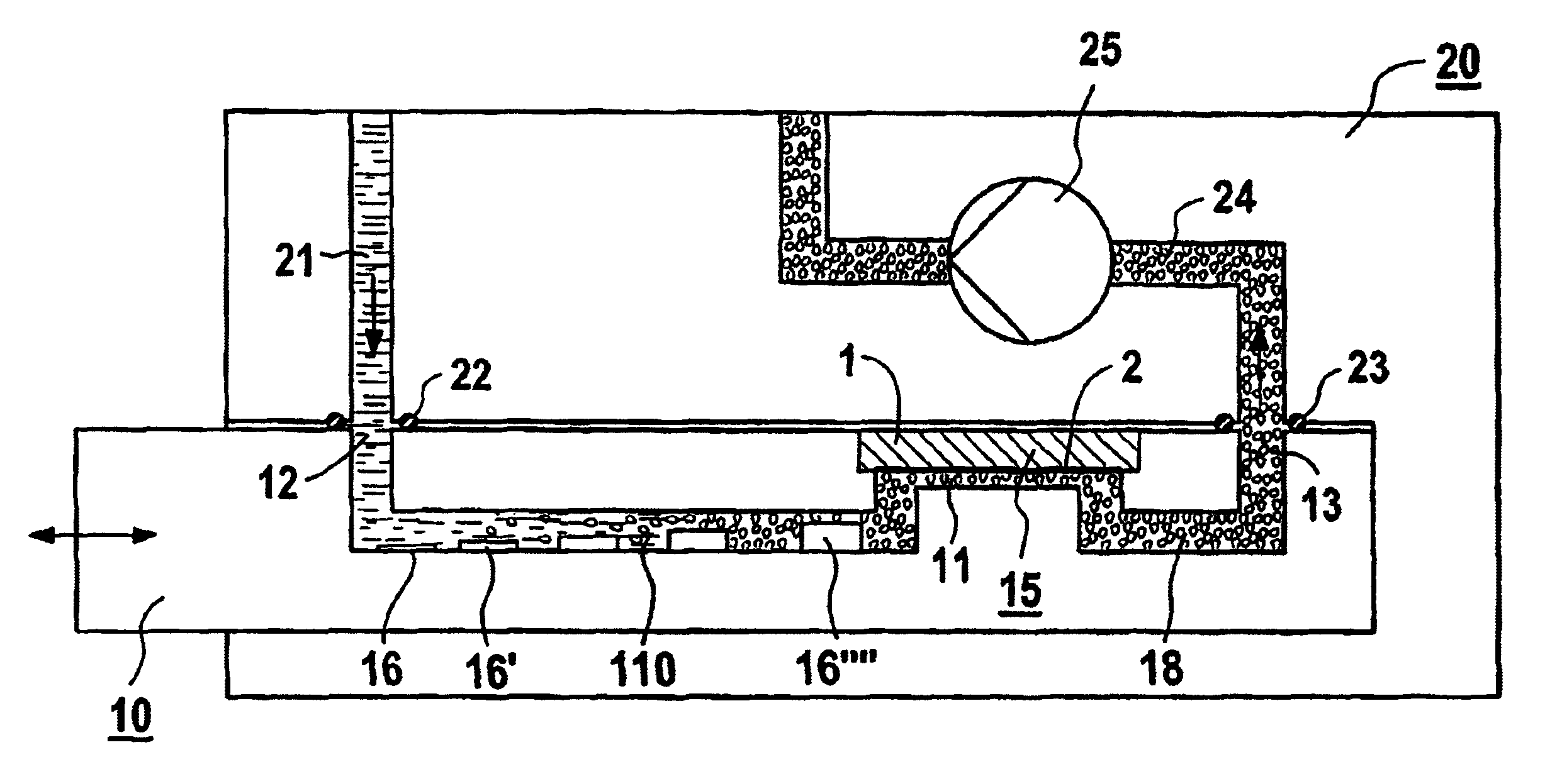
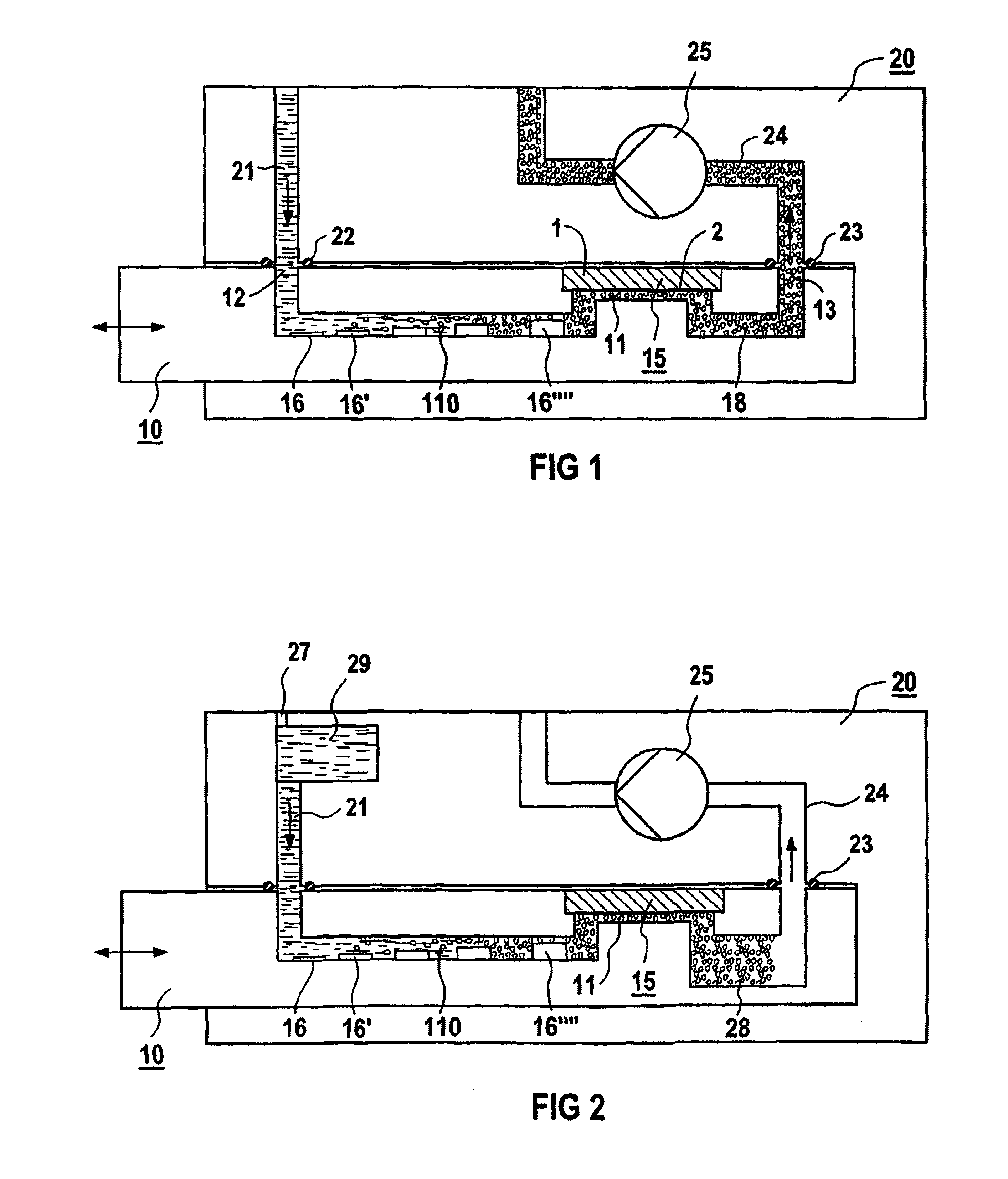
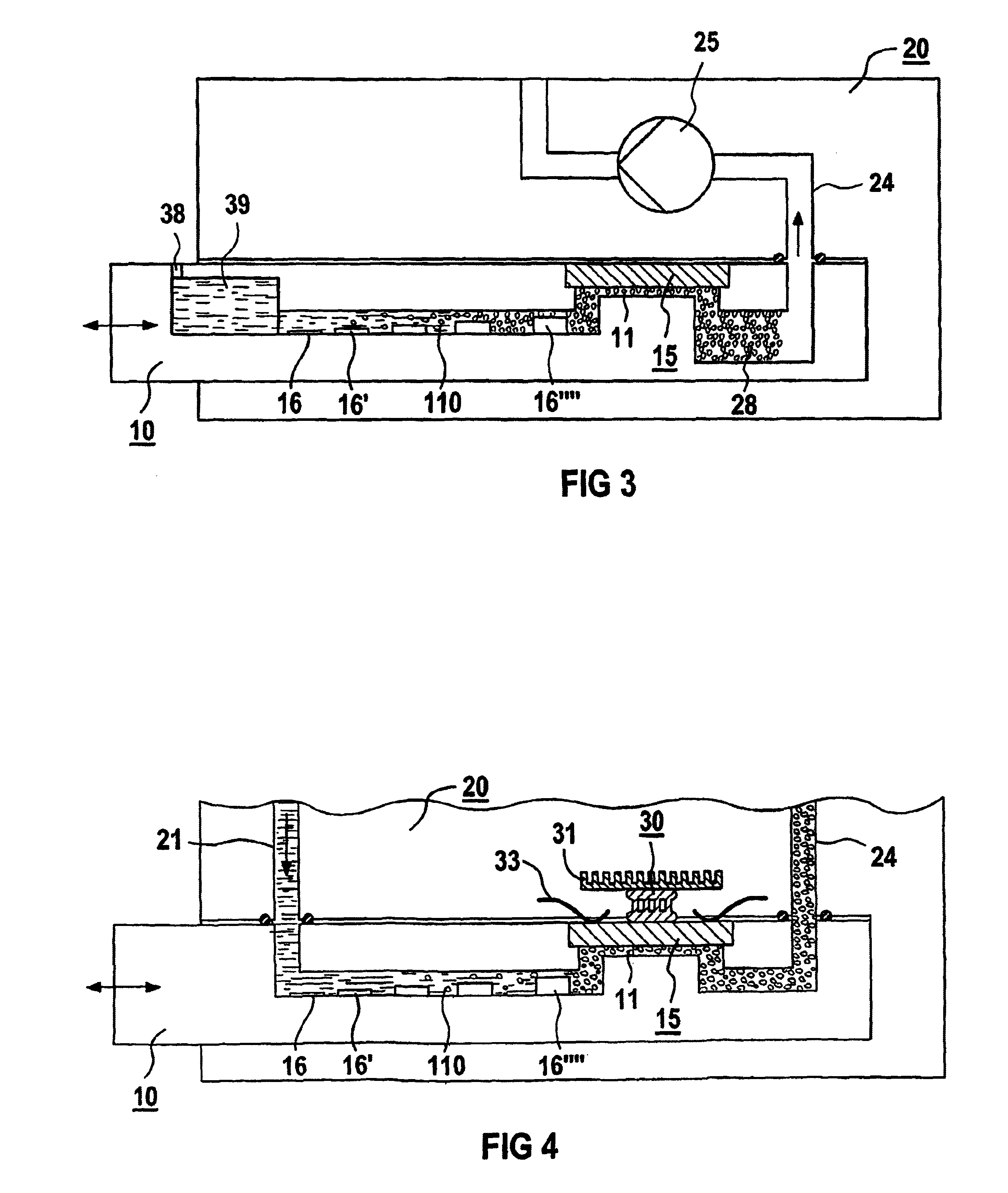
[0027]In FIGS. 1 to 4, an applicator with a sensor module is designated throughout by 10, while in FIGS. 6 and 7 a modified applicator is designated by 60 or 70. For measuring, such an applicator 10, 60 or 70 is pushed into a reader 20 or 80.

[0028]In FIGS. 1 to 3, a sensor module 15, for example a silicon chip 1 with a sensitive area 2, has been introduced into the applicator 10, encapsulated and electrically contacted on a carrier. Such a sensor module is the subject, inter alia, of a corresponding patent application with the same priority. On the sensor module 15 there is a microfluidic channel 11, to which a channel 110, in which reagents or adjuvants 16, 16′, . . . , 16′″ are arranged, leads from an inlet 12 with a valve arrangement / seal. Behind the senso...


PUM

PropertyMeasurementUnit
temperatureaaaaaaaaaa
temperaturesaaaaaaaaaa

Abstract

A microfluidic diagnosis kit used in biochemical analysis obtains a premeasured amount of reagents in an applicator for an analysis system. The required reagents are proportioned as non-volatile agents and a microfluidic system is provided, whereby the reagents are automatically dissolved in a solvent and fed to a sensor module to carry out measurement.

Description

CROSS REFERENCE TO RELATED APPLICATIONS[0001]This application is based on and hereby claims priority to German Application No. 101 11 457.5 filed on Mar. 9, 2001, the contents of which are hereby incorporated by reference. This application is related to MODULE FOR AN ANALYSIS DEVICE, APPLICATOR AS AN EXCHANGE PART OF THE ANALYSIS DEVICE AND ANALYSIS DEVICE ASSOCIATED THEREWITH, filed concurrently by Walter Gumbrecht, Manfred Stanzel, Manfred Wossler and Jörg Zapf and incorporated by reference herein.BACKGROUND OF THE INVENTION[0002]1. Field of the Invention[0003]The invention relates to an analysis device for use in biochemical analytics, with an applicator for decentralized use, containing a first housing, a fluidic system and a sensor module, which together with a second housing forms a measuring and analysis system.[0004]2. Description of the Related Art[0005]One of the requirements for the decentralization of chemical-biological analyses in medical technology is that reagents ar...

Claims


Application Information

Patent Timeline
Patent Type & Authority Patents(United States)
IPC IPC(8): G01N27/00G01N35/08A61B5/145A61B5/1468A61B5/1495B01L3/00B01L7/00B01L9/00C12M1/00C12M1/34G01N27/416G01N35/00G01N37/00
CPCB01L3/502715B01L3/52B01L7/52B01L9/527B01L2200/027B01L2200/16B01L2300/0645B01L2300/0816B01L2300/0867B01L2300/1822B01L2400/0487G01N27/416
Inventor GUMBRECHT, WALTERSTANZEL, MANFRED
Owner BOEHRINGER LNGELHEIM VETMEDICA GMBH
Why Eureka
Try Eureka