
Inspection system and inspection process utilizing magnetic inspection vehicle

a magnetic inspection and inspection system technology, applied in the direction of television systems, carpet cleaners, instruments, etc., can solve the problems of requiring worker protection, affecting the safety of workers,

Active Publication Date: 2013-12-10
ROLLS ROYCE CONTROL SYST HLDG CO
View PDF13 Cites 16 Cited by
  • Summary
  • Abstract
  • Description
  • Claims
  • Application Information

AI Technical Summary

Benefits of technology

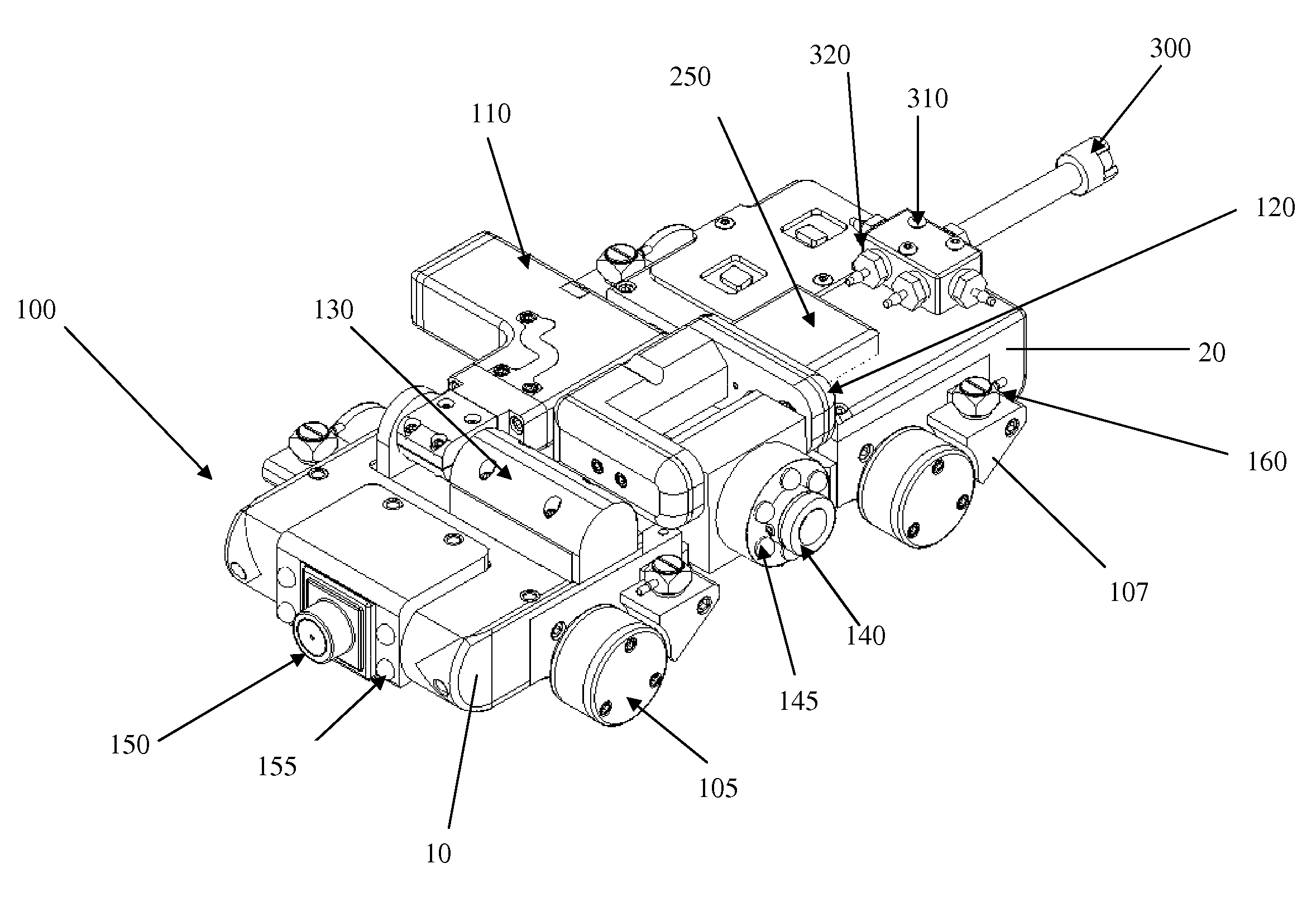
The present invention provides an inspection vehicle for inspecting steam generators. The vehicle has a front chassis and a rear chassis with two independently driven magnetic wheels that can move relative to each other. The vehicle also has a navigation camera and a pan and tilt inspection camera assembly that can be stowed within the vehicle. The inspection vehicle can automatically orient itself to a set orientation. The method includes inserting the inspection vehicle through a handhole on the secondary side of the steam generator and inspecting the tubesheet, U-tubes, and flow distribution baffle in a sequential manner. The technical effects of the invention include improved inspection efficiency and ease of use for inspecting steam generators.

Problems solved by technology

Given the importance of steam generator tube integrity, PWR licensees have technical specifications governing the surveillance of steam generator U-tubes, but such technical specifications typically do not prescribe nondestructive test methods for inspecting tubes or specify where a particular methodology should be used, as is noted in Generic Letter (GL) 2004-01 issued by the U.S. Nuclear Regulatory Commission.
To satisfy such requirements and guidelines, inspections were previously carried out by manually pushing video probes into the steam generator, which was and is disadvantageously radiation dose intensive (requires worker protection and limitation of exposure time), or by using inspection crawlers, which could inspect the annulus region, but could not inspect the annular region and the in-bundle high-flow region between the tubesheet and the first tube support.

Method used


Image

  • Inspection system and inspection process utilizing magnetic inspection vehicle
  • Inspection system and inspection process utilizing magnetic inspection vehicle
  • Inspection system and inspection process utilizing magnetic inspection vehicle

Examples


Embodiment Construction

[0039]While this invention is susceptible of embodiment in many different forms, there is shown in the drawings and will herein be described in detail preferred embodiments of the invention with the understanding that the present disclosure is to be considered as an exemplification of the principles of the invention and is not intended to limit the broad aspect of the invention to the embodiments illustrated.

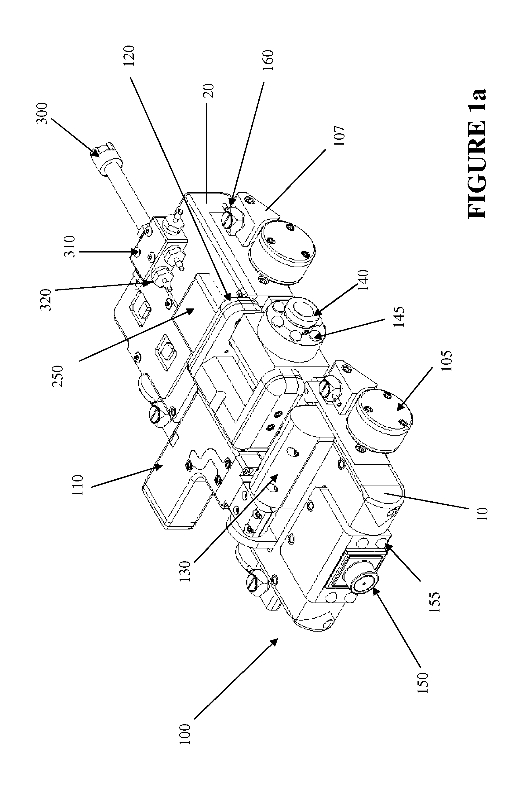
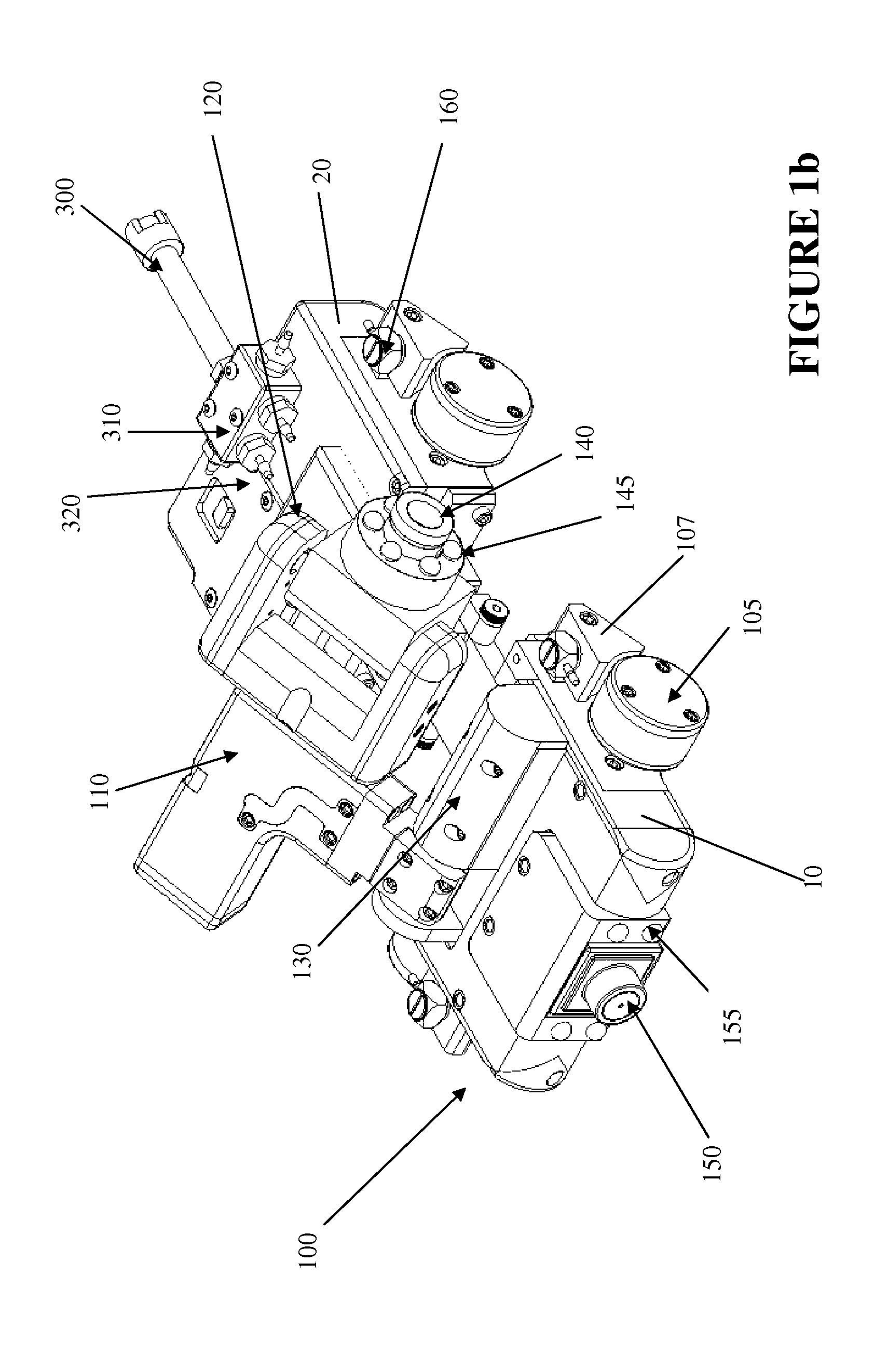
[0040]The presently disclosed concepts relate, in at least some aspects, to an inspection system utilizing a magnetic inspection vehicle 100 and, more particularly, to a steam generator shell wrapper annulus inspection system comprising a magnetic inspection vehicle 100, such as is shown by way of example in FIGS. 1a-1p. The inspection system disclosed herein comprises a remote camera system deployed in combination with an inspection vehicle 100, such inspection system being configured to thereby perform visual inspections, such as to perform observation of the presence of free ...


PUM


Abstract

An inspection vehicle configured to inspect steam generators includes a front chassis having two independently driven magnetic wheels, a rear chassis having two independently driven magnetic wheels, and a connecting member flexibly connecting the front chassis to the rear chassis to permit relative motion between the front chassis and the rear chassis along at least one axis. The connecting member, front chassis, and rear chassis collectively define a receiving area. The inspection vehicle also includes a navigation camera disposed on the front chassis and a pan and tilt inspection camera assembly including a first rotatable arm driven by a first motor, a second rotatable arm disposed on a distal portion of the first rotatable arm, the second rotatable arm being driven by a second motor, and an inspection camera rotatably disposed on a distal portion of the second arm, the inspection camera being driven by a third motor, the camera assembly being dimensioned to be received within the receiving area in a stowed position.

Description

CLAIM TO PRIORITY[0001]This application claims priority from 61 / 156,121, filed on Feb. 27, 2009, which is incorporated by reference herein in its entirety.FIELD OF THE INVENTION[0002]This invention relates to a method and apparatus for inspecting a steam generator and, more particularly, to a method and apparatus for remotely inspecting steam generator internals.BACKGROUND OF THE INVENTION[0003]In a pressurized water reactor (PWR), the heat generated by the nuclear reaction on the primary side is passed to reactor coolant. The reactor coolant is, in turn, passed into a hot leg of a steam generator (e.g., a Westinghouse Model 51 steam generator), moves through U-tubes (the “tube bundle”) in the steam generator (passing heat into water on the secondary side of steam generator), and passes out through a “cold” leg of the steam generator to return to the reactor to complete and perpetuate the loop.[0004]The PWR steam generator typically is an upright cylindrical pressure vessel with hem...

Claims


Application Information

Patent Timeline
Patent Type & Authority Patents(United States)
IPC IPC(8): H04N7/18
CPCF22B37/002F22B37/38G21C17/013B25J5/00B62D57/02G01M3/00
Inventor WEBSTER, BRIANBATES, NATHANPUDLO, BRYAN
Owner ROLLS ROYCE CONTROL SYST HLDG CO
Learn More