Clamping device for a telescopic rod

a technology of telescopic rods and clamping devices, which is applied in the direction of rod connections, couplings, machine supports, etc., can solve the problem that the lugs cannot be easily fatigued, and achieve the effect of smooth displacemen

Active Publication Date: 2013-12-17
HSIN YUAN LAI
View PDF22 Cites 50 Cited by
  • Summary
  • Abstract
  • Description
  • Claims
  • Application Information

AI Technical Summary

Benefits of technology

[0006]An object of the present invention is to provide a clamping device which can prevent malfunction in clamping caused by fatigue of a flexible sleeve thereof to thereby ensure smoothness of a length-adjustment of a telescopic rod.
[0008]By provision of the elastic lining member which acquires a biasing force when the first and second lugs are in the tightened position, the first and second lugs can be urged away from each other once the tightening force by virtue of the camming action of the camming surface is released, and can be smoothly displaced back to the untightened position. Furthermore, the first and second lugs will not easily become fatigue with prolonged use.

Problems solved by technology

Furthermore, the first and second lugs will not easily become fatigue with prolonged use.

Method used


Image

  • Clamping device for a telescopic rod
  • Clamping device for a telescopic rod
  • Clamping device for a telescopic rod

Examples


first embodiment

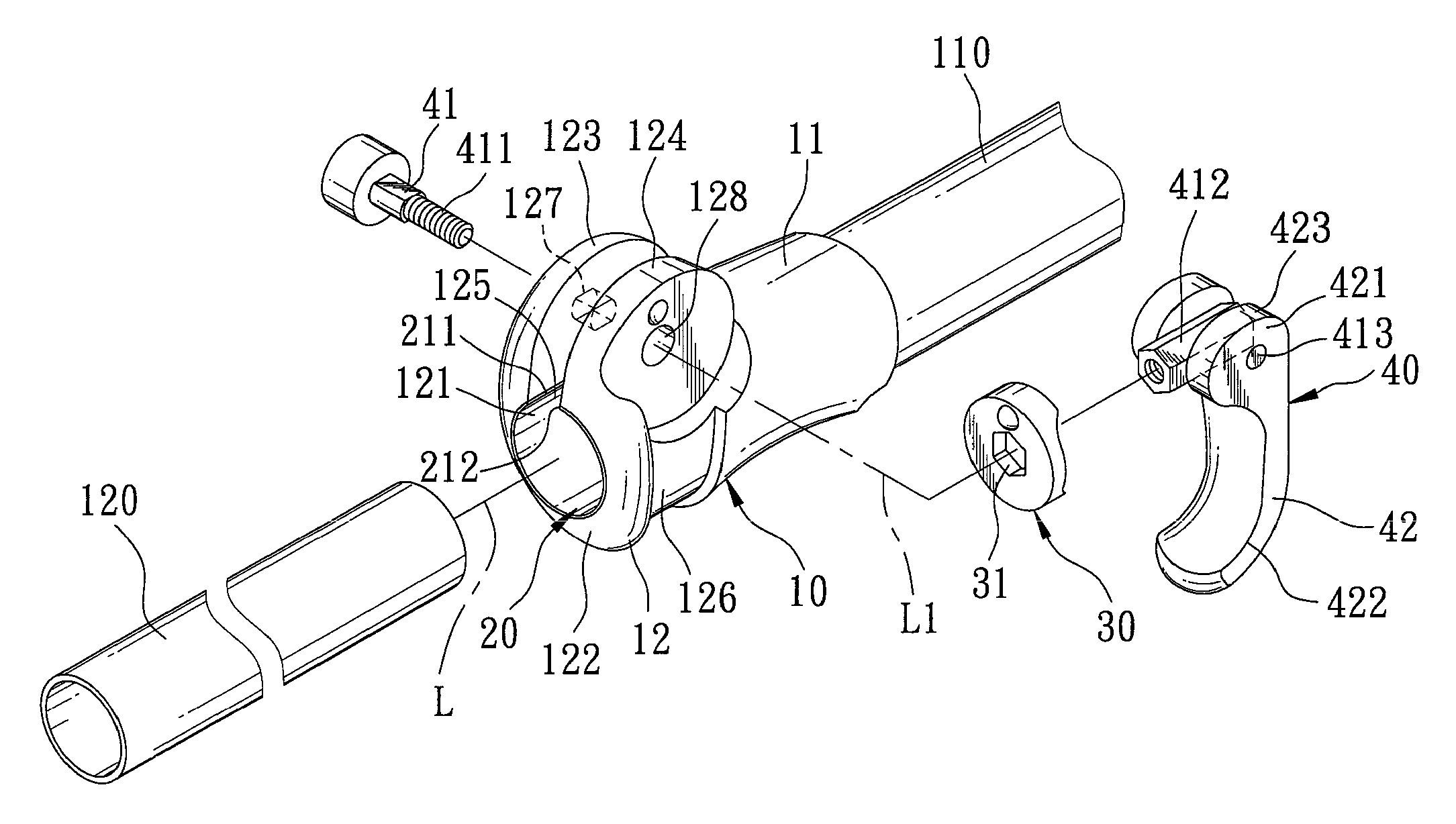
[0020]Referring to FIGS. 3 and 4, a clamping device according to the present invention is shown to be mounted at the joint ends of outer and inner segments 110, 120 of a telescopic rod that are telescopically fitted to each other along a longitudinal axis (L). The clamping device comprises a flexible sleeve 10, an elastic lining member 20, a tightening washer 30, and a tightening unit 40.

[0021]The flexible sleeve 10 has a mount portion 11 adapted to be secured on the joint end of the outer segment 110, a collar 12 which has a grasping surface 122 that circumscribes an axially extending bore 121 along the longitudinal axis (L) for receiving the joint end of the inner segment 120, and which has a gap 125 that extends axially and that is communicated with the axially extending bore 121 to define two opposite side edges, and first and second lugs 123, 124 which respectively extend from the side edges in a first transverse direction relative to the longitudinal axis (L), and which are sp...

third embodiment

[0029]Referring to FIG. 8, in the clamping device, the collar 12″ of the flexible sleeve 10″ has a protective layer 13 which extends from the grasping surface 122″ to cover the entire breadth of the elastic lining member 20″ to thereby prevent the elastic lining member 20″ from direct contact with the joint end of the inner segment 120. Specifically, the elastic lining member 20″ is engaged in the flexible sleeve 10″ to be spaced apart from the grasp surface 122″ by the protective layer 13.

fourth embodiment

[0030]Referring to FIG. 9, in the clamping device, the elastic lining member 200 further has a circumferentially extending flange 240 which extends radially from outer end edges of the base lining segment 201 and the curved flanking segments 202 and which is in abutting engagement with an outer end edge of the collar 12 opposite to the mount portion 11 so as to prevent axial movement of the elastic lining member 200 along the longitudinal axis (L). Hence, the elastic lining member 200 can be press-fitted in the axially extending bore 121 of the collar 12.


PUM


Abstract

A clamping device includes a flexible sleeve secured to one segment of a telescopic rod and having a collar for receiving the other segment, and two lugs displaceable between untightened and tightened positions, and an elastic lining member disposed on the collar such that, as a result of displacement of the lugs from the untightened position to the tightened position, the elastic lining member is strained to acquire a biasing force that biases the lugs back toward the untightened position, thereby facilitating telescopic movement of the telescopic rod during length-adjustment.

Description

BACKGROUND OF THE INVENTION[0001]1. Field of the Invention[0002]This invention relates to a telescopic rod, more particularly to a clamping device for clamping two segments of a telescopic rod.[0003]2. Description of the Related Art[0004]Referring to FIGS. 1 and 2, a conventional clamping device for a length-adjustable pole as disclosed in U.S. Publication No. 2011 / 0240078 A1 is shown to include a flexible sleeve 1 having a collar 101 which is secured to one segment of a telescopic rod, and a pair of lugs 102, 104 defining a gap 103 therebetween. A bolt 2 has a threaded stem extending through the lugs 102, 104 to engage a screw nut 4. A washer 3 is sleeved on a head of the bolt 2. A lever arm 5 is pivotably connected to the head about a hinge axis 501, and has a cam surface 502 to be in abutting engagement with the washer 3. Upon turning of the lever arm 5, by virtue of a camming action between the cam surface 502 and the washer 3, the lugs 102, 104 are displaced between clamped and...

Claims


Application Information

Patent Timeline
Patent Type & Authority Patents(United States)
IPC IPC(8): F16L3/08F16L1/12
CPCF16B7/1454Y10T403/7071Y10T24/44265Y10T403/595Y10T403/7066
Inventor LAI, HSIN-YUAN
Owner HSIN YUAN LAI
Why Eureka
Try Eureka