Dispenser part

a dispenser and part technology, applied in the field of dispenser parts, can solve the problems of seams that cannot withstand the forces expected to be withstand, at least the first component may be damaged, and the dispenser may be exposed to accidental or intentional point loading, etc., to achieve the effect of facilitating melting

Active Publication Date: 2013-12-17
ESSITY HYGIENE & HEALTH AB
View PDF37 Cites 10 Cited by
  • Summary
  • Abstract
  • Description
  • Claims
  • Application Information

AI Technical Summary

Benefits of technology

[0025]In order to achieve a desired strength each corner of the said steps, or each projection, is arranged to melt during the second injection moulding step. It has been found that by providing steps formed by substantially right angled corners along the entire length of the seam, the formation of a homogenous, strong seam is achieved. When the molten material injected during the second injection moulding step reaches the solidified edge of the first part, the corners or projections facilitate the melting together of the first and second parts. In order to ensure this, the temperature of the material to be injected and / or the temperature or one or both mould may be controlled to achieve the desired result. For instance, the temperature of the material injected at least during the second injection moulding step may be selected above the recommended injection temperature for the particular material. As the second material flows through the mould towards the first part, its temperature will gradually drop. However, as the initial temperature at the start of the injection is higher than normal, the temperature of the molten second material will still be sufficient to melt the edge of the solidified first part. The temperature of the first part may be controlled by adjusting the cooling of the mould. The first part is retained in the mould after the first injection moulding step, in order to maintain the shape of the first part as it begins to cool and to maintain the first part at an elevated temperature until the second injection moulding step has been completed. The finished dispenser part may then be cooled and removed from the mould.

Problems solved by technology

A dispenser part manufactured in this way may have problems with distortion of at least the first component, as well as of the seam, in particular in or near the regions of the side edges.
The component parts are usually joined end-to-end and even with local reinforcements, the seam may lack sufficient strength to withstand the forces it may be expected to withstand.
For example, the front of the dispenser may be exposed to accidental or intentional point loading, such as an impact force caused by an object or a person striking the dispenser.
A weak seam may cause the dispenser part making up the cover to crack along at least part of the front surface, requiring the dispenser part to be replaced.

Method used


Image

  • Dispenser part
  • Dispenser part
  • Dispenser part

Examples


Embodiment Construction

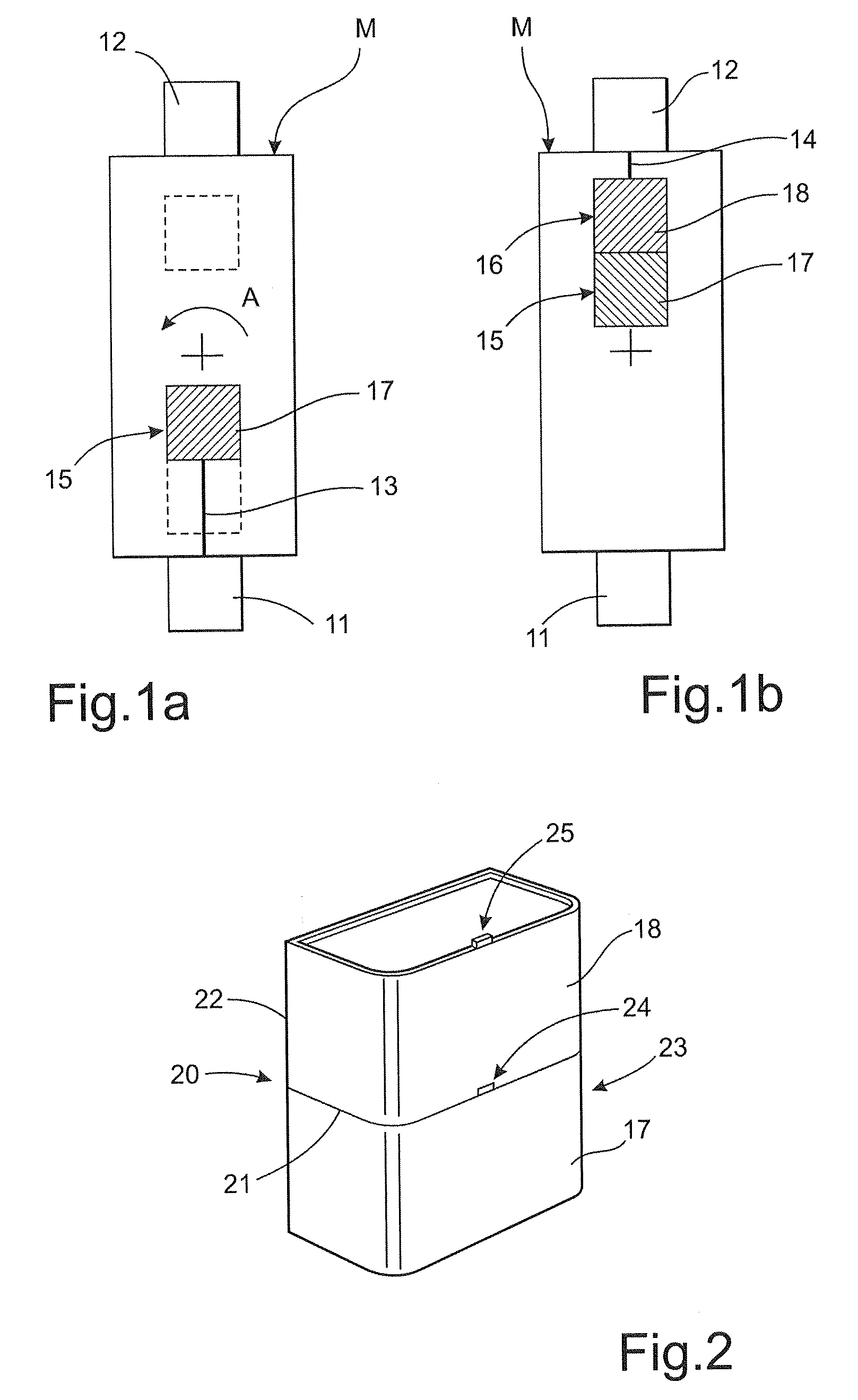
[0070]FIGS. 1A and 1B show a schematic illustration of an arrangement for carrying out a two component injection moulding process for making a dispenser part according to the invention.

[0071]In this example, the process uses two injection units 11, 12 and a rotary mould M designed for sequential injection of a single part using two different materials. In the subsequent text the process is described for the injection of a transparent and an opaque material, but it is applicable for any combination of transparent and / or coloured materials. The mould M used in this example is a two cavity mould. The mould M is held closed in a first cavity position shown in FIG. 1A and heated to a predetermined operating temperature. The first material, which is usually the material having the highest injection temperature, is injected from the first injection unit 11 through a primary runner system 13 into a first cavity 15 to form a first component 17. In this example, the first material is a transp...


PUM

PropertyMeasurementUnit
thicknessaaaaaaaaaa
thicknessaaaaaaaaaa
thicknessaaaaaaaaaa

Abstract

A dispenser part, such as a dispenser or a part of a dispenser, includes a first injection molded plastic component part having an associated first mating surface; a second injection molded plastic component part having an associated second mating surface; and a seam formed by the first mating surface and the second mating surface during injection molding for joining the first component part and the second component part to define a dispenser part. The resulting seam has a strength equal to or greater than the strength of at least one of the first and second molded plastic component parts.

Description

TECHNICAL FIELD[0001]The present invention concerns dispenser parts, in particular dispensers or parts of dispensers, comprising at least two component parts selected from a range of plastic materials, which components may be joined along a seam extending from a first side edge to a second side edge of the dispenser part.BACKGROUND ART[0002]In many types of dispensers it is for various reasons often desirable to provide a dispenser part where at least an outer surface, a shell or a similar dispenser part is made from two similar or different plastic materials. For instance, it is possible to make one section of the dispenser part transparent, in order to facilitate checking of the level of a consumable product contained within the dispenser. A second section can be made opaque in order to hide a dispensing mechanism, to allow monitoring of the filling level and to provide a dispenser with an aesthetically pleasant appearance.[0003]When making such a dispenser part, the first compone...

Claims


Application Information

Patent Timeline
Patent Type & Authority Patents(United States)
IPC IPC(8): B65D6/28
CPCB29C45/1657B29K2055/02Y10T403/47Y10T428/195Y10T428/192
Inventor ZAJTAI, CSABAPOCZIK, IMRE
Owner ESSITY HYGIENE & HEALTH AB
Why Eureka
Try Eureka