
Fence apparatus and related methods

a technology of fence apparatus and related methods, applied in the field of fence structure, can solve the problems of increased shipping costs for less fence length, laborious manufacture of framed wire fence panels, and difficulty in handling, so as to improve handling capabilities, reduce labor intensity, and improve shipping efficiency

Active Publication Date: 2013-12-24
LARSEN CHARLES
View PDF76 Cites 3 Cited by
  • Summary
  • Abstract
  • Description
  • Claims
  • Application Information

AI Technical Summary

Benefits of technology

The modular design enhances shipping efficiency, reduces handling difficulties, and lowers manufacturing and shipping costs by allowing panels to nest securely, thus increasing the linear feet of fence that can be shipped while maintaining structural stability.

Problems solved by technology

Although relatively stiff and although they provide various benefits, such wire frame panels have a number of drawbacks.
For example, the manufacture of framed wire fence panels is generally considered labor intensive (and therefore relatively expensive), since the process involves manually attaching the wire mesh fill to the framing material.
In addition, frames such as the familiar tubular type post used in many applications substantially increase freight weight, handling difficulty, and bulkiness, which typically results in greater shipping costs for less fence length when compared to a fence panel without such bulky posts.
Even if the tubular posts / frames are shipped separately, the total shipping weight for the assembly remains the same (although under such a “ship unassembled” approach, the intensive labor needed to assemble the fence is left to the end user).

Method used


Image

  • Fence apparatus and related methods
  • Fence apparatus and related methods
  • Fence apparatus and related methods

Examples


Embodiment Construction

[0053]Embodiments of the present invention will now be described with references to the accompanying Figures, with like reference numerals referring to like elements throughout. The terminology used in the description presented is not intended to be interpreted in any limited or restrictive manner, simply because it is being utilized in conjunction with a detailed description of certain embodiments of the invention. Furthermore, various embodiments of the invention (whether or not specifically described) may include novel features, no single one of which may be solely responsible for its desirable attributes or which may be essential to practicing the invention. The description herein and claims below are instead intended to describe and define the invention in a manner supporting the broadest scope of coverage to which the claims may be lawfully entitled.

[0054]General wire mesh or reticulated wire structure making methods such as those described in U.S. Pat. No. 2,401,319 to Roemer...


PUM

PropertyMeasurementUnit
angleaaaaaaaaaa
lengthaaaaaaaaaa
areaaaaaaaaaaa

Abstract

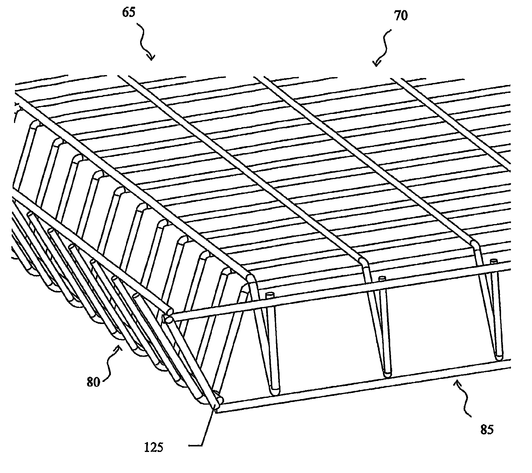
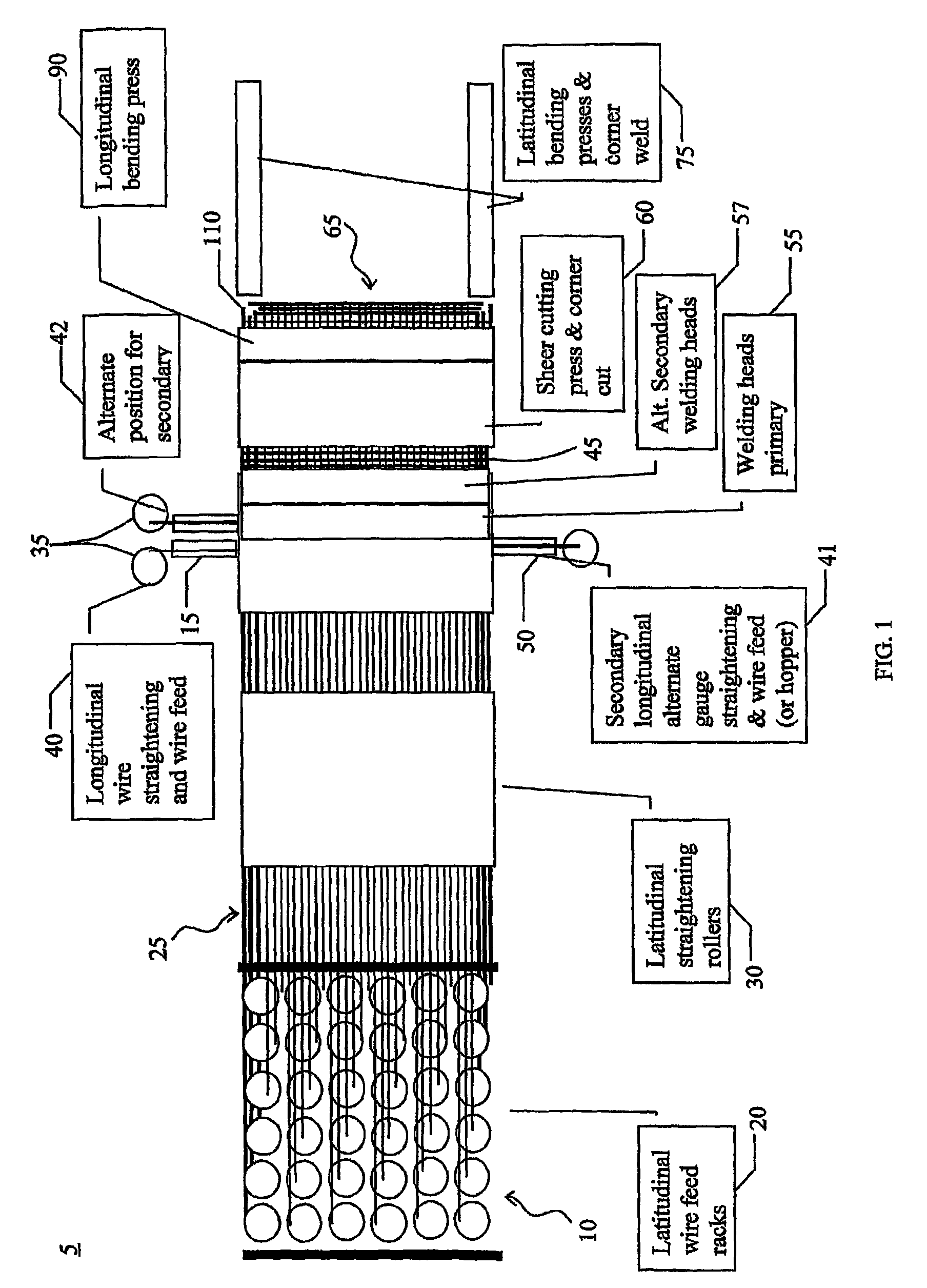
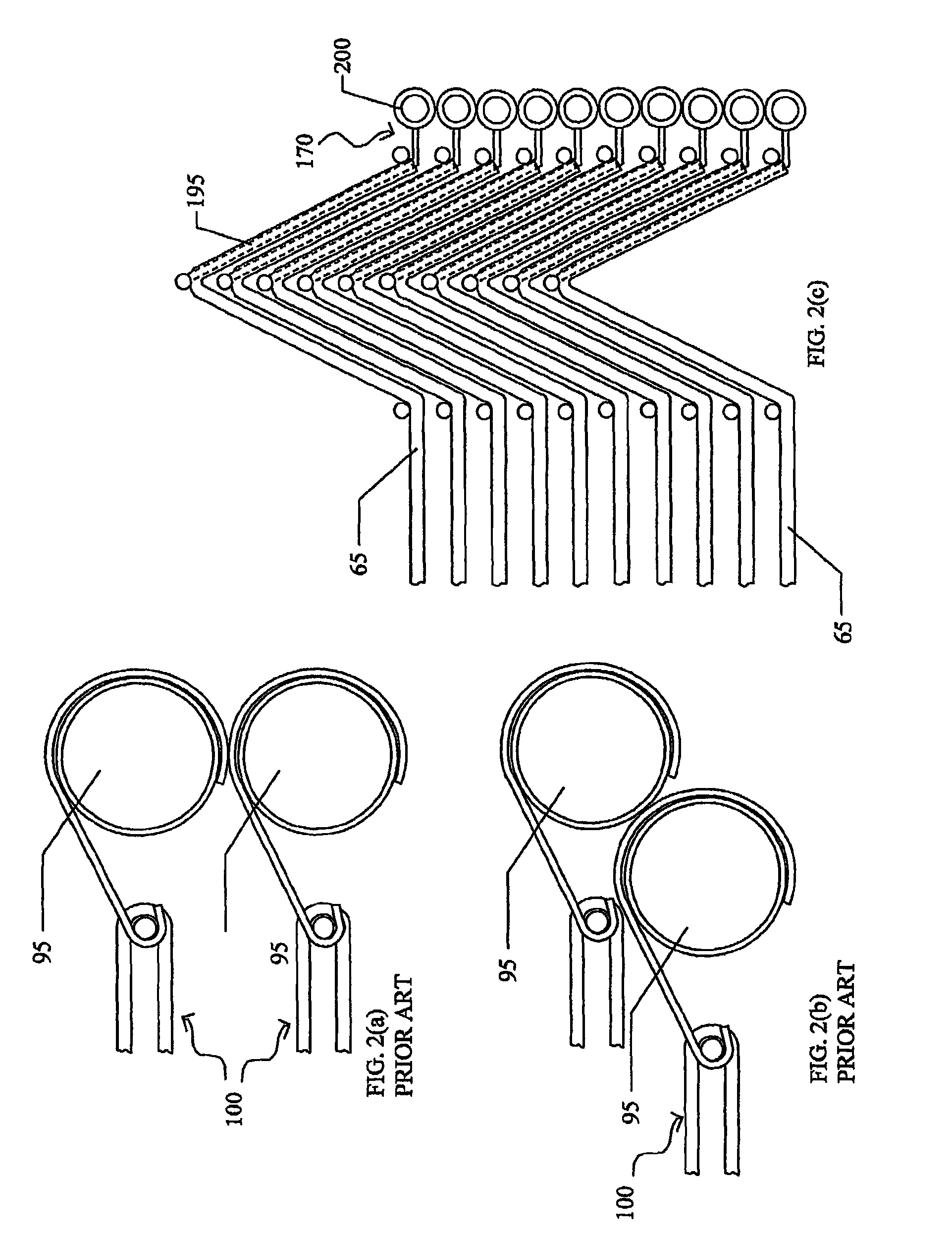
The present invention is directed to a fence or enclosure (165) and related methods for making a fence panel (65) and for connecting the panel (65) to other panels (65) to form a modular type fence (165). The invention preferably includes a generally planar section (70) of fencing material formed from spaced-apart wires (10, 15), and at least two non-parallel stiffening portions (80, 85) deforming the fence section (65) from the aforementioned generally planar configuration (70).

Description

CROSS-REFERENCE TO RELATED APPLICATION[0001]This application claims priority to PCT application serial no. PCT / US05 / 29132 filed Aug. 17, 2005 which claims priority to U.S. application Ser. No. 10 / 920,650 filed Aug. 18, 2004.FIELD OF THE INVENTION[0002]The present invention relates generally to a fence structure. More particularly, the present invention relates to a generally planar fence panel having surface stiffening means that provide for, among other things, improved strength-to-weight characteristics, nesting and convenient packaging of a plurality of similar panels, and related methods of manufacture.INCORPORATION BY REFERENCE[0003]The contents of each U.S. patent or other reference, if any, cited in this application, are hereby incorporated by reference.BACKGROUND OF THE INVENTION[0004]A wide range of fence types are available for residential and commercial applications including, among other uses, an enclosure; boarding, or containment structure such as a cage, pen, or kenne...

Claims


Application Information

Patent Timeline
Patent Type & Authority Patents(United States)
IPC IPC(8): B23P11/00B23P17/00
CPCE04H17/161Y10T29/49838Y10T29/49829Y10T29/49966
Inventor LARSEN, CHARLES
Owner LARSEN CHARLES
Learn More