Combined water hose and temperature-operated water flow valve and associated method

a technology of water flow valve and water hose, which is applied in the direction of valve operating means/release devices, process and machine control, etc., can solve the problems of affecting the performance the installation of the water flow valve for heating swimming pools and hot tubs costs several thousands of dollars, and the disadvantages of the available heating assembly are significant, so as to achieve the effect of not losing its resilien

Inactive Publication Date: 2013-12-24
ANDERSON DAVID B
View PDF5 Cites 8 Cited by
  • Summary
  • Abstract
  • Description
  • Claims
  • Application Information

AI Technical Summary

Benefits of technology

[0012]The temperature-operating water flow valve may include a hollow body preferably having axially offset proximal and distal open ends respectively such that the body may have an internal temperature. A temperature-activated plunger release mechanism may be seated inside the body and intermediately positioned between the proximal and distal open ends respectively. The temperature-activated plunger release mechanism may be automatically reciprocated along a linear travel path as the internal temperature rises above a threshold internal temperature and falls below the threshold internal temperature respectively. In this way, the temperature-activated plunger release mechanism may automatically open and close during the reciprocation along the linear travel path such that heated water is respectively permitted and prohibited to egress the distal open end of the body.
[0013]The energy of the sun may be utilized to heat the water contained within the hose. Thus, heated water is selectively released from the valve at a predetermine temperature. Such an arrangement provides the unexpected and unpredicted advantage of using the radiant heat of the sun to heat the cold water within the hose and further release the heated water into a swimming pool for example, thus saving energy costs for a user.
[0015]The hollow body may further include a valve seat inwardly protruding towards a center of the body such that a maximum diameter of the valve seat is less than a maximum diameter of the body. A second piston may be connected to the stem and removably conjoined to the valve seat. A deformably resilient spring may be fixedly attached to the second piston. A second retention plate may be engaged with the spring and located at the distal open end of the body. The second retention plate preferably has a plurality of openings formed therein for permitting the heated water to egress the body. Such an arrangement provides the unexpected and unpredictable advantage of providing a small and compact release mechanism linearly arranged within the valve body that can be fitted to a conventional hose adaptor without the use of intervening elements.
[0017]The wax pellet may be selectively designed to melt at a particular temperature or over a specific temperature range. In this way, the expansion of the wax pellet increases surface area contact with an interior wall of the shell and thereby linearly urges the first piston and the stem axially away from the first retention plate. The linear movement of the stem causes the second piston to disengage the valve seat and thereby permit water to flow downstream of the second retention plate. Such an arrangement provides the unexpected and unpredicted advantage of providing a temperature-activated automatic release mechanism for discharging the heated water from the hose.
[0018]The spring may be compressed along the linear travel path when the second piston is disengaged from the valve seat. The spring automatically returns to equilibrium when the second piston linearly retracts and engages the valve seat and thereby prohibits water to flow downstream of the second piston. Of course, the spring may be calibrated to have a force, which is overcome by the force of the expanding wax. In this manner, the spring may be reciprocated a multiple of times without losing its resilience. Such an arrangement provides the unexpected and unpredictable advantage of repeatedly utilizing the temperature-operated water flow valve without risking premature failure of such a mechanism.
[0019]The second retention plate may include a linear rod protruding upstream therefrom such that the spring may be concentrically wound thereabout. In this manner, the spring remains concentrically aligned about a central longitudinal axis passing through the body and thereby ensures the second piston is uniformly displaced along the linear travel path.

Problems solved by technology

In some cases, however, the available heating assemblies have significant disadvantages.
An example of an extremely costly and wasteful use of heat for comfort and pleasure is a heated swimming pool or hot tub.
The installation for heating swimming pools and hot tubs costs several thousands of dollars, and many hundreds of dollars have to be spent for fuel each year.
Unfortunately, there is no convenient low-cost means of allowing such solar heating applications to automatically release the heated water when it has reached a desired temperature.

Method used


Image

  • Combined water hose and temperature-operated water flow valve and associated method
  • Combined water hose and temperature-operated water flow valve and associated method
  • Combined water hose and temperature-operated water flow valve and associated method

Examples


Embodiment Construction

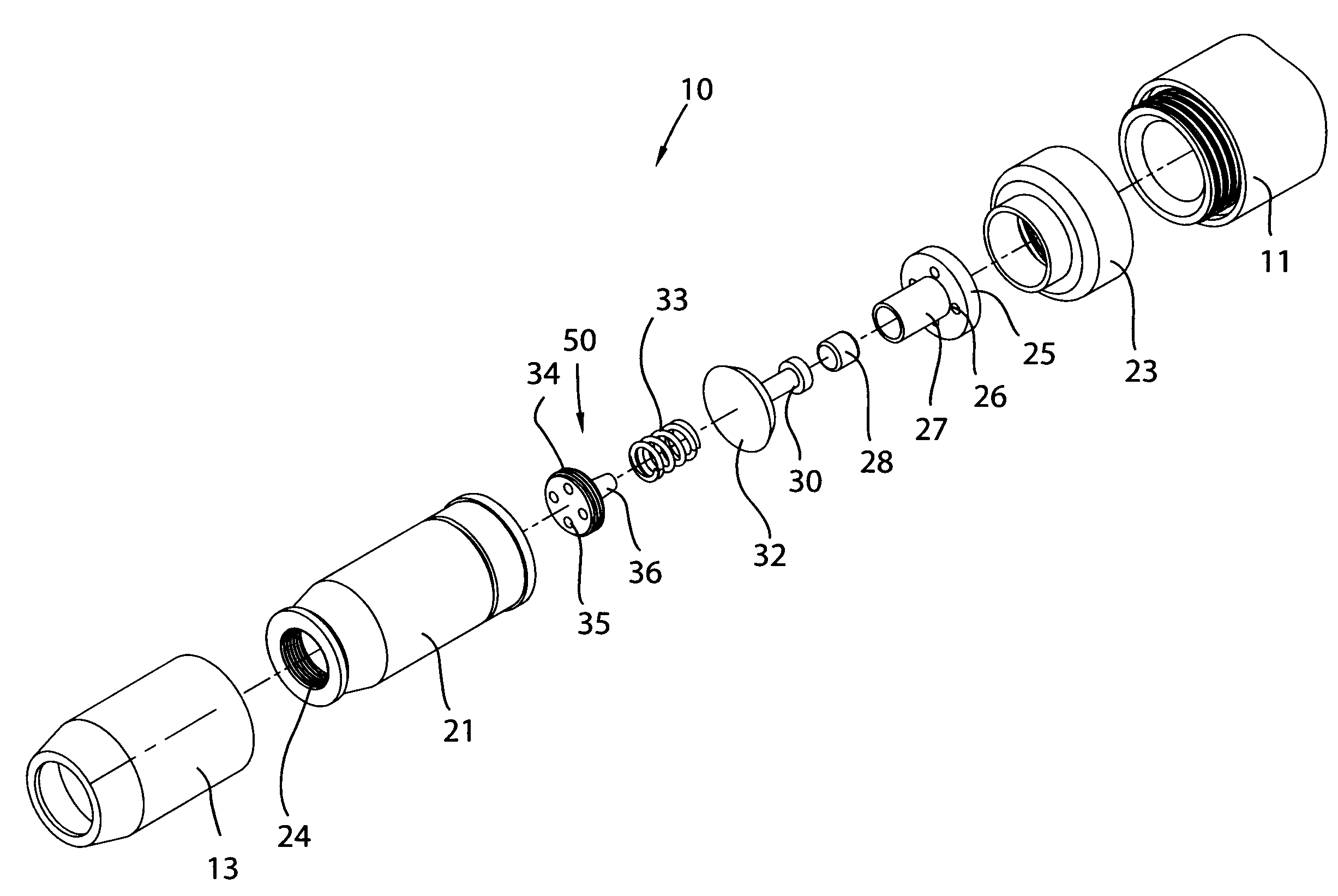
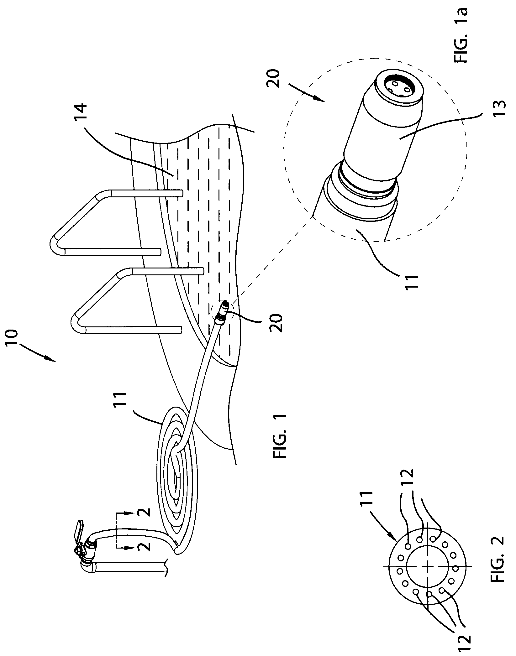
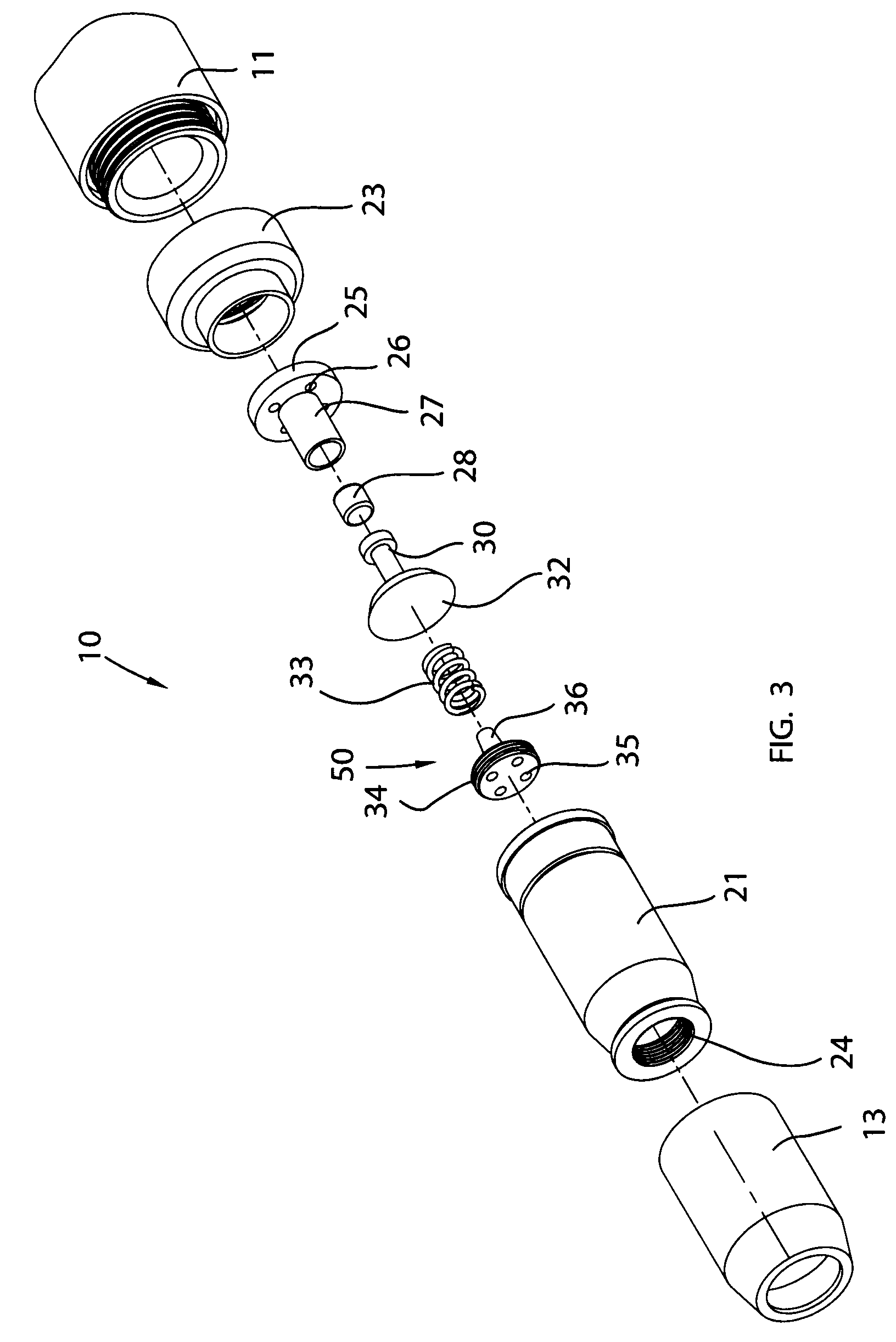
[0034]The present invention will now be described more fully hereinafter with reference to the accompanying drawings, in which a preferred embodiment of the invention is shown. This invention may, however, be embodied in many different forms and should not be construed as limited to the embodiment set forth herein. Rather, this embodiment is provided so that this application will be thorough and complete, and will fully convey the true scope of the invention to those skilled in the art. Like numbers refer to like elements throughout the figures.

[0035]The illustrations of the embodiments described herein are intended to provide a general understanding of the structure of the various embodiments. The illustrations are not intended to serve as a complete description of all of the elements and features of apparatus and systems that utilize the structures or methods described herein. Many other embodiments may be apparent to those of skill in the art upon reviewing the disclosure. Other ...


PUM


Abstract

A temperature-operating water flow valve may include a hollow body having axially offset proximal and distal open ends respectively such that the body may have an internal temperature. A temperature-activated plunger release mechanism may be seated inside the body and intermediately positioned between the proximal and distal open ends respectively. The temperature-activated plunger release mechanism may be automatically reciprocated along a linear travel path as the internal temperature rises above a threshold internal temperature and falls below the threshold internal temperature respectively. A temperature-activated plunger release mechanism may automatically open and close during the reciprocation along the linear travel path such that heated water is respectively permitted and prohibited to egress the distal open end of the body.

Description

CROSS REFERENCE TO RELATED APPLICATIONS[0001]This application claims the benefit of U.S. Provisional Application No. 61 / 215,705, filed May 8, 2009, the entire disclosures of which are incorporated herein by reference.STATEMENT REGARDING FEDERALLY SPONSORED RESEARCH OR DEVELOPMENT[0002]Not Applicable.REFERENCE TO A MICROFICHE APPENDIX[0003]Not Applicable.BACKGROUND OF THE INVENTION[0004]1. Technical Field[0005]This invention relates to water flow valves and, more particularly, to a temperature-activated water flow valve for providing users with a convenient means of automatically discharging the flow of heated water from a water hose to a swimming a pool.[0006]2. Prior Art[0007]In a variety of forms, warmth is relaxing and pleasurable to most people—basking in the sun; sitting by an open fire or a woodstove; reclining in a hot bath, whirlpool or spa; dressing in a warm room; a warm, dry towel after a shower or bath—all of these experiences are enjoyable. Many of them require some for...

Claims


Application Information

Patent Timeline
Patent Type & Authority Patents(United States)
IPC IPC(8): G05D23/02
CPCB05B1/3013G05D23/022F16K3/00B05B12/10F16K31/002
Inventor ANDERSON, DAVID B.
Owner ANDERSON DAVID B
Why Eureka
Try Eureka