Sheet storing apparatus and image forming apparatus

a technology of image forming apparatus and storage apparatus, which is applied in the directions of electrographic process, transportation and packaging, instruments, etc., can solve the problems of deteriorating sheet disorder, and deterioration of removability, so as to improve the visibility and removability of stored sheets.

Inactive Publication Date: 2013-12-24
CANON KK
View PDF7 Cites 6 Cited by
  • Summary
  • Abstract
  • Description
  • Claims
  • Application Information

AI Technical Summary

Benefits of technology

[0009]According to the present invention, a sheet can be held with permitting sheet transit in a sheet conveying direction while restricting sheet movement in a direction opposite to the sheet conveying direction, which can improve the visibility and removability of the stored sheet.

Problems solved by technology

Therefore, there is difference in height among the bin trays, which deteriorates visibility and removability of the sheet stored in the bin tray especially located at a low position.
Therefore, a sheet may be disordered in the bin tray due to a sheet condition (such as curl and skin friction) at the discharge, or the sheet bundle may erroneously touch another sheet bundle when removing it out of the bin tray.
As a result, removability is deteriorated and trouble such as discharge error may be caused.
Furthermore, the conventional sheet storing apparatus is placed on a side of the image forming apparatus, which causes a problem that a length in a width direction of a whole system including the image forming apparatus and the sheet storing apparatus is increased.

Method used


Image

  • Sheet storing apparatus and image forming apparatus
  • Sheet storing apparatus and image forming apparatus
  • Sheet storing apparatus and image forming apparatus

Examples


first exemplary embodiment

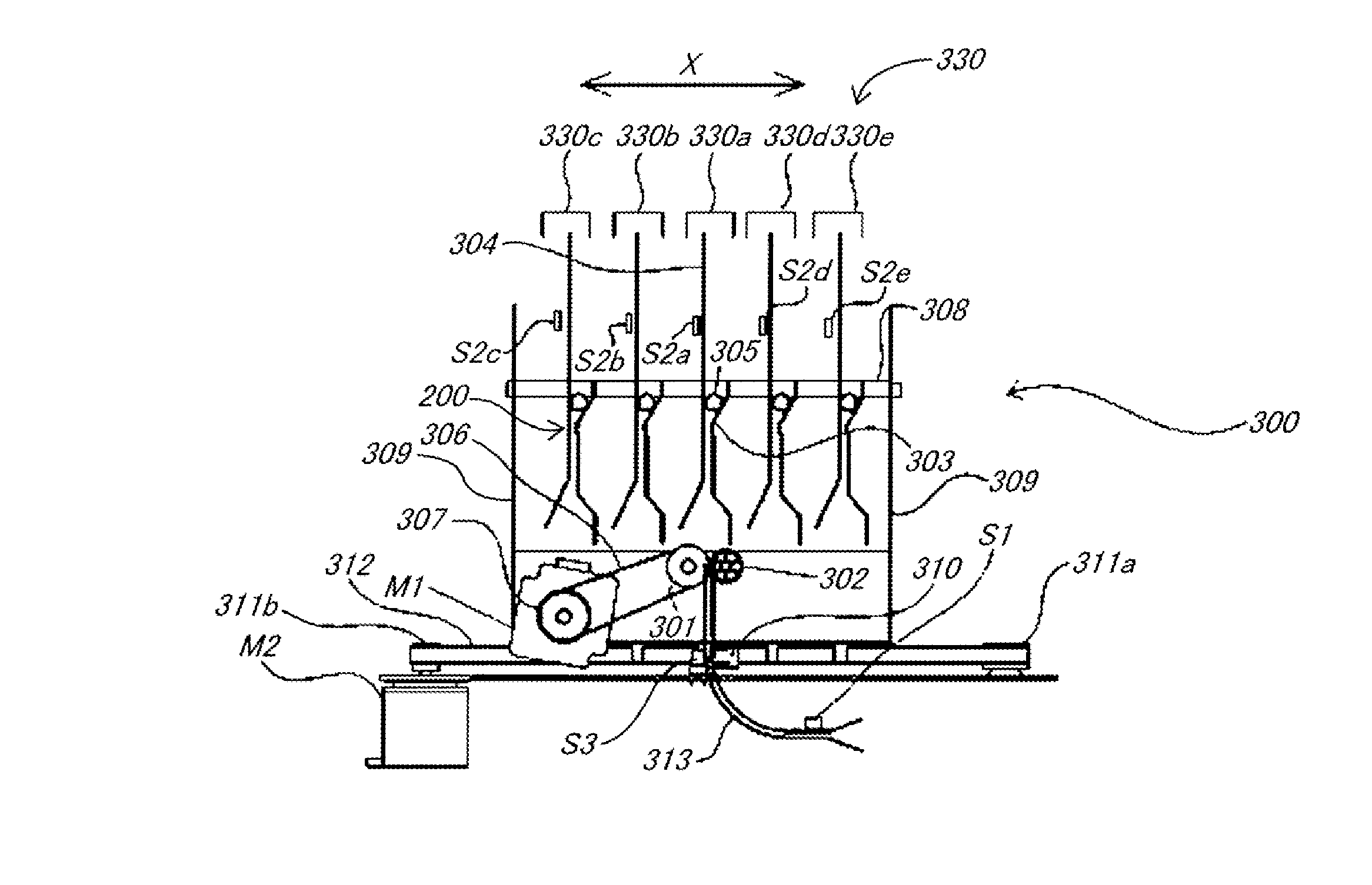
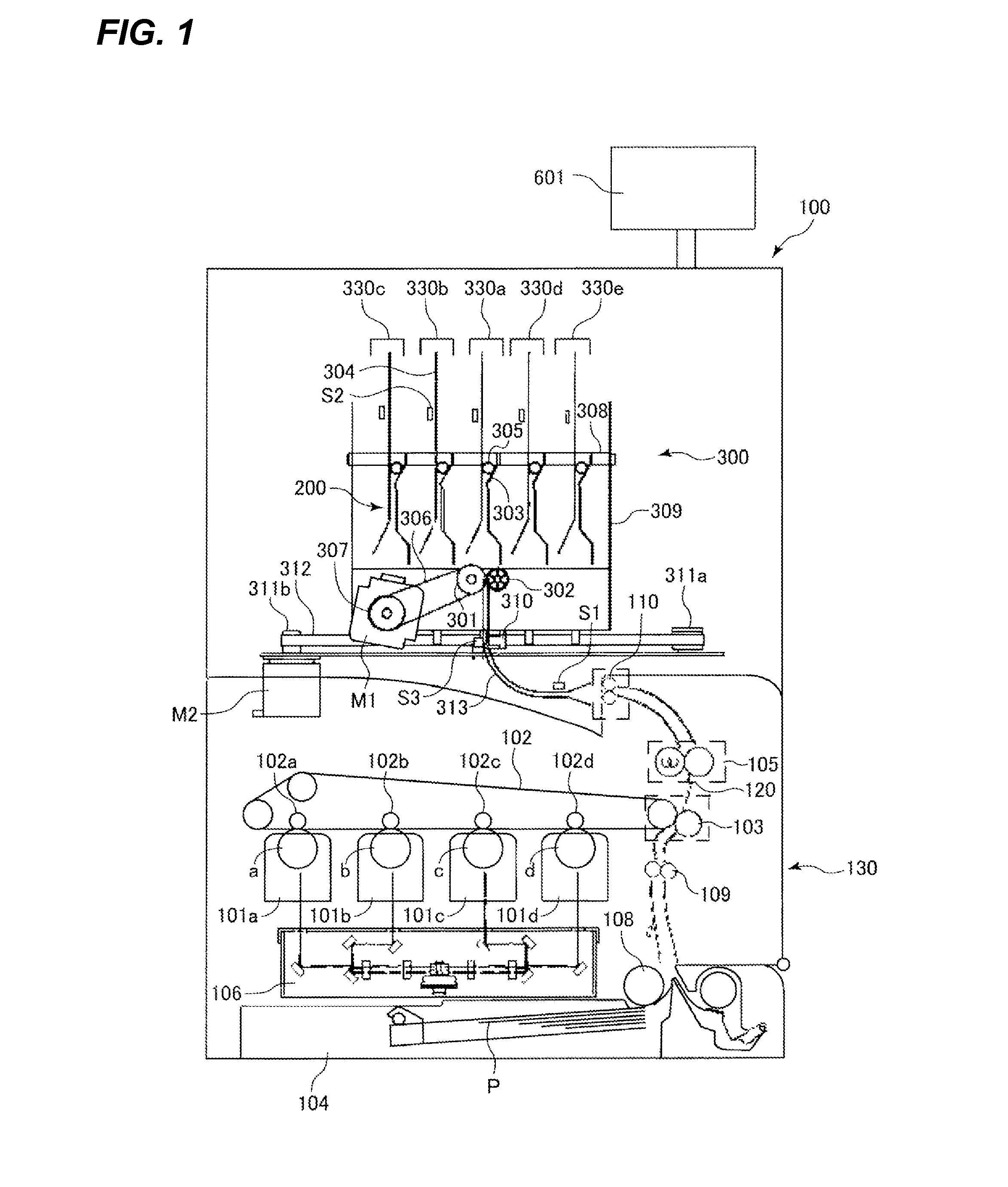
[0036]A color copying machine 100 as an image forming apparatus according to an exemplary embodiment of the present invention will be described with reference to FIG. 1. The color copying machine 100 has a copying machine body 130 as an image forming apparatus body and a sheet storing apparatus 300 provided above and connected to the copying machine body 130. The color copying machine 100 has an image forming portion for forming an image (to be described later) and sheet storing portions 330a to 330e for storing a sheet P conveyed with the image formed by the image forming portion. Since use of the sheet storing apparatus 300 is optional, the copying machine body 130 is so configured as to be usable separately from the sheet storing apparatus 300. Alternatively, the sheet storing apparatus 300 and the copying machine body 130 may be integrally constructed.

[0037][Image forming apparatus] Next, the copying machine body 130 will be described. The copying machine body 130 has a photosen...

second exemplary embodiment

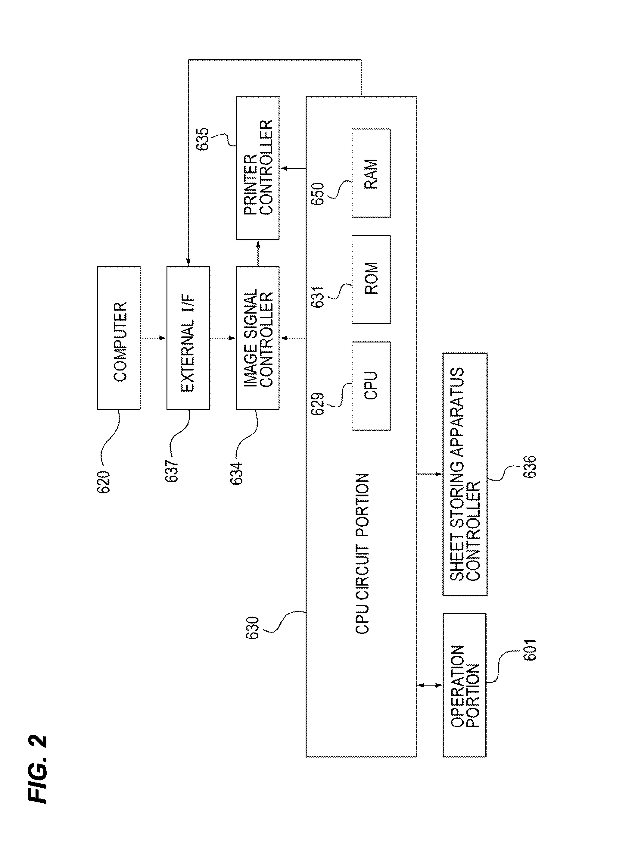
[0099]Next, a sheet storing apparatus 300 and a color copying machine 100 according to a second exemplary embodiment of the present invention will be described with reference to FIGS. 15 to 17. In the present exemplary embodiment, the same reference numerals are given to the same components as those described in the first exemplary embodiment and an overlapping description will be omitted as appropriate. Moreover, the I / Os of such as motors and sensors are the same as in the case of the first exemplary embodiment, and the block diagram is omitted. Furthermore, the sheet storing operation flow also is the same as in the case of the first exemplary embodiment, and the flow chart is omitted.

[0100]Each of sheet storing portions 330a to 330e constituting five sheet storing portions 330 (330a to 330e) in the present exemplary embodiment will be described in detail with reference to FIGS. 15A and 15B. FIG. 15A is a cross-sectional view illustrating an example of a sheet holding portion 340...

third exemplary embodiment

[0119]Next, an image forming apparatus 100A according to a third exemplary embodiment of the present invention will be described with reference to FIGS. 18 to 24. Description related to FIG. 1 is incorporated herein. The image forming apparatus 100A according to the third exemplary embodiment is different in a sheet storing portion 330A of a sheet storing apparatus 300A from the foregoing first and second exemplary embodiment. Therefore, the difference from the first and second exemplary embodiments, namely, the sheet storing portion 330A will be mainly described in the third exemplary embodiment. The same reference numerals are given to the same components as those described in the first and second exemplary embodiments, and an overlapping description will be omitted as appropriate. It should be noted that the same configuration in the third exemplary embodiment as that described in the first and second exemplary embodiments provides the same effects as in the first and second exem...


PUM

PropertyMeasurementUnit
angleaaaaaaaaaa
inclination angleaaaaaaaaaa
angleaaaaaaaaaa

Abstract

A conveying roller conveys a sheet. A sheet holding portion receives a sheet from below and holds the received sheet with keeping its forward end upward and its rear end downward. The sheet holding portion has: a storing guide provided in a vertical state and having a guide surface configured to guide the received sheet upward; a conveying guide provided to face the guide surface and having a curved surface portion whose distance from the guide surface increases in the upward direction; and a holding member provided between the guide surface and the curved surface portion and configured to roll on the curved surface portion toward the guide surface to nip the received sheet with the guide surface. An inclination angle of the curved surface portion with respect to the guide surface decreases with distance from the guide surface.

Description

BACKGROUND OF THE INVENTION[0001]1. Field of the Invention[0002]The present invention relates to a sheet storing apparatus and an image forming apparatus, and particularly to an image forming apparatus above which a sheet storing apparatus is disposed.[0003]2. Description of the Related Art[0004]An image forming apparatus having a sheet storing apparatus is conventionally known. The sheet storing apparatus is provided for storing a sheet discharged from the image forming apparatus body, and sheets on which an image is formed are sequentially discharged to the sheet storing apparatus. For example, U.S. Pat. No. 5,722,030 discloses an image forming apparatus having a bin moving type sorter. In the sorter, a plurality of bin trays capable of storing a sheet on which an image is formed is so provided as to be movable in a vertical direction.[0005]However, according to the sheet storing apparatus of the image forming apparatus disclosed in U.S. Pat. No. 5,722,030, the bin tray is provide...

Claims


Application Information

Patent Timeline
Patent Type & Authority Patents(United States)
IPC IPC(8): B65H31/08
CPCG03G15/6552B65H29/52B65H31/02B65H2301/42142B65H2405/20B65H2405/211B65H2405/3312B65H2408/112B65H2801/06
Inventor GAMO, YOHEITOKUMA, NAOTOIWATA, TOSHIYUKI
Owner CANON KK
Why Eureka
Try Eureka