Lance for injecting solid material into a vessel

a solid material and vessel technology, applied in the direction of blast furnace components, manufacturing converters, blast furnaces, etc., can solve the problems of premature failure of the weld connecting the adjacent sections of a wear resistant material, failure of the lance, etc., to minimise the risk of the lance failure, the weld is difficult to reliably weld, and the requirements are quite separate

Active Publication Date: 2013-12-24
TATA STEEL
View PDF12 Cites 1 Cited by
  • Summary
  • Abstract
  • Description
  • Claims
  • Application Information

AI Technical Summary

Benefits of technology

[0019]Constructing the core tube assembly of the lance with the outer tube of a structural material and the inner tube of a wear resistant material optimises the quite separate requirements for the core tube assembly, particularly in situations where the lance is relatively long (i.e. at least 4 m) and is used to inject hot (i.e. greater than 600° C.), abrasive materials. In addition, bonding the inner and the outer tubes together is particularly advantageous in situations where the core tube assembly comprises a number of axially aligned sections that have to be secured together. By way of explanation, it is often the case that wear resistant materials, such as ferrochromium white cast iron, are difficult to weld reliably and, hence, there is a real risk that welds connecting together adjacent sections of a wear resistant material may fail prematurely, and ultimately lead to failure of the lance. Bonding the inner tube and the outer tube together provides an opportunity to avoid this issue. Moreover, where a core tube assembly comprises a plurality of sections, the outer tube provides an opportunity to minimise any risks of failure of the lance even in situations where the inner tube is segmented rather than a continuous tube because, typically, structural materials that are suitable for use for the outer tube can be welded together with a high degree of weld integrity. In addition, the bonding between the outer tube and the inner tube can extend at least substantially across the whole of the surface area of the interface between the two tubes and thereby provide resistance to shear forces experienced by such tubes arising from pneumatic conveying of materials through the passageway of the core tube assembly into the vessel.

Problems solved by technology

By way of explanation, it is often the case that wear resistant materials, such as ferrochromium white cast iron, are difficult to weld reliably and, hence, there is a real risk that welds connecting together adjacent sections of a wear resistant material may fail prematurely, and ultimately lead to failure of the lance.

Method used


Image

  • Lance for injecting solid material into a vessel
  • Lance for injecting solid material into a vessel
  • Lance for injecting solid material into a vessel

Examples


Embodiment Construction

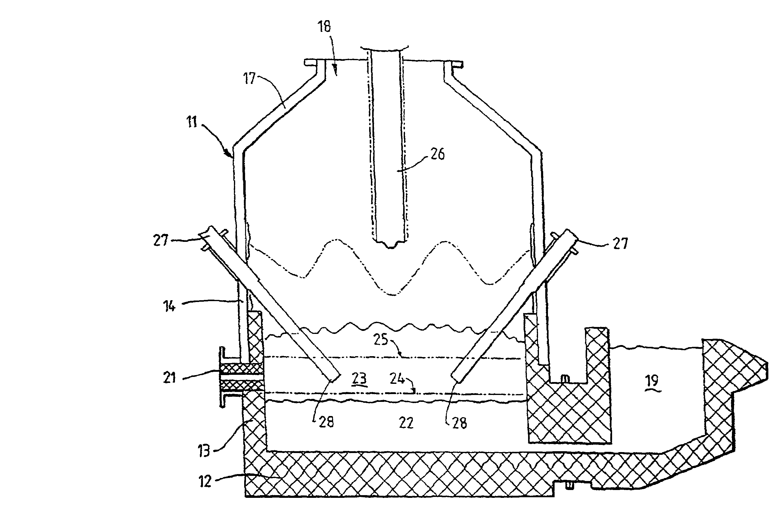
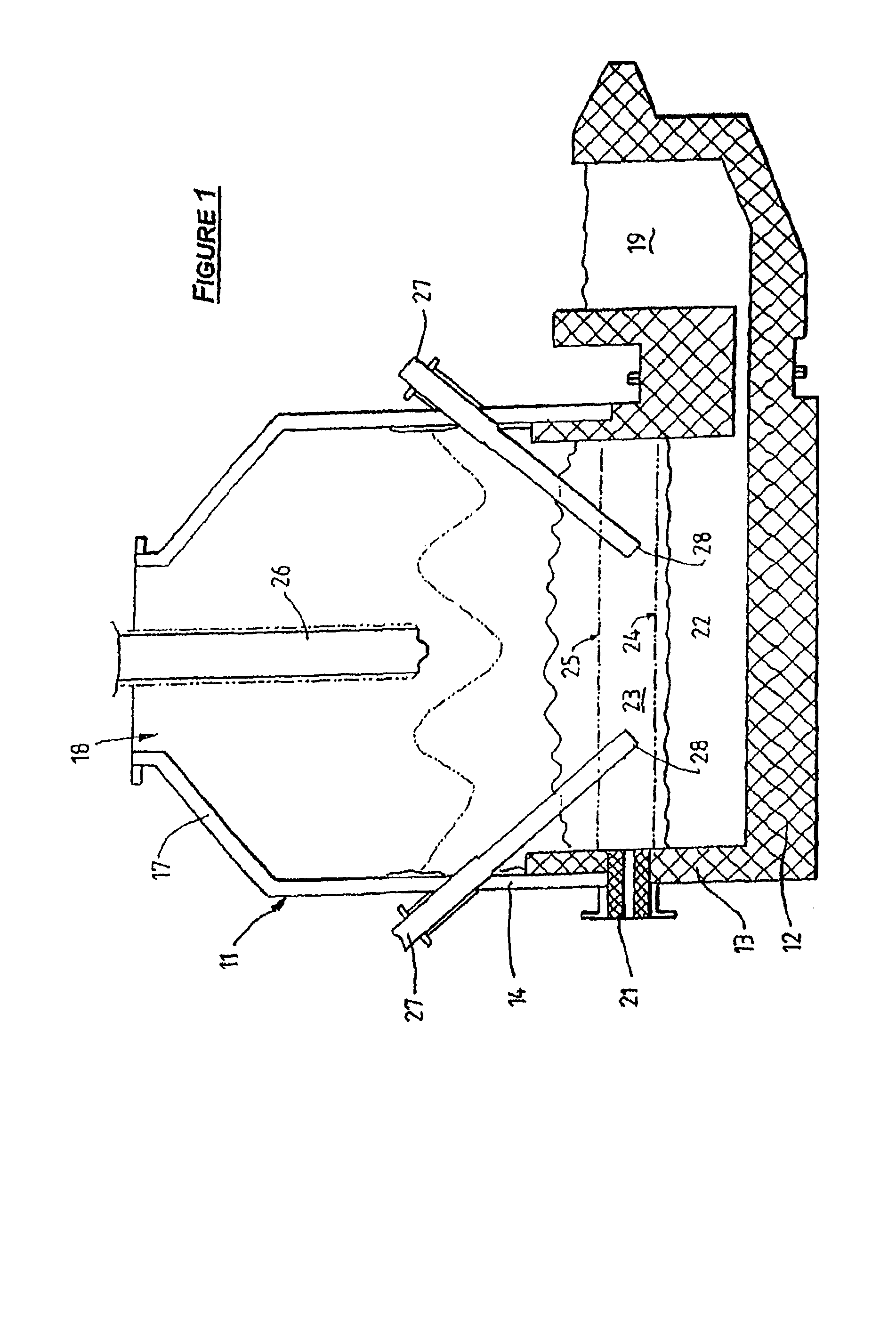
[0053]FIG. 1 shows a direct smelting vessel 11 that is suitable particularly for carrying out the HIsmelt process as described in International patent application PCT / AU96 / 00197. The following description is in the context of smelting iron ore fines to produce molten iron in accordance with the HIsmelt process. It will be appreciated that the present invention is applicable to smelting any metalliferous material, including ores, partly reduced ores, and metal-containing waste streams. It will also be appreciated that the ores can be in the form of iron ore fines. It will also be appreciated that the present invention is not confined to producing iron and extends to smelting other metals (including alloys).

[0054]The vessel 11 has a hearth that includes a base 12 and sides 13 formed from refractory bricks, side walls 14, which form a generally cylindrical barrel extending upwardly from the sides 13 of the hearth, and a roof 17. Water-cooled panels (not shown) are provided for transfer...


PUM

PropertyMeasurementUnit
thickaaaaaaaaaa
thicknessaaaaaaaaaa
thicknessaaaaaaaaaa

Abstract

A lance for injecting a solid material into a vessel, such as a direct smelting vessel for producing molten iron, has a core tube assembly comprising a passageway for solid material. The core tube assembly has an inlet for receiving solid material at a rear end and an outlet for discharging material at a forward end. The core tube assembly comprises an outer tube of a structural material and an inner tube of a wear resistant material that are bonded together. A method of manufacturing the core tube assembly may include spin casting the outer tube of the structural material; spin casting the inner tube of the wear resistant material onto the inner surface of the outer tube; and metallurgically bonding the tubes together.

Description

CROSS REFERENCE TO RELATED APPLICATIONS[0001]This application is a National Phase application based on PCT / AU2008 / 000888 filed on Jun. 19, 2008, the contents of which are incorporated herein by reference and claims the priority of Australian Application No. 2,007,903,287, filed on Jun. 19, 2007, the contents of which are incorporated herein by reference.FIELD OF THE INVENTION[0002]The present invention relates to a lance for injecting solid material into a vessel, such as a direct smelting vessel for producing molten iron.BACKGROUND[0003]A known direct smelting process, which relies principally on a molten bath as a reaction medium, and is generally referred to as the HIsmelt process, is described in International application PCT / AU96 / 00197 (WO 96 / 31627) in the name of the applicant.[0004]The HIsmelt process as described in the International application in the context of producing molten iron includes:[0005](a) forming a bath of molten iron and slag in a vessel;[0006](b) injecting i...

Claims


Application Information

Patent Timeline
Patent Type & Authority Patents(United States)
IPC IPC(8): C21C7/04
CPCC21B11/08C21B13/0013C21C5/4613F27B1/16F27B1/20F27B1/21F27B3/18F27D3/16F27D3/18Y02P10/134
Inventor MINKO, BRONISLAW JERZY
Owner TATA STEEL
Why Eureka
Try Eureka