Systems and methods for protecting a receiving antenna from interference by a transmitting antenna

a transmitting antenna and receiving antenna technology, applied in direction finders, direction finders using radio waves, instruments, etc., can solve the problems of other signals in the environment, such as those intended for the victim antenna, not being coherent with the signals from the main and auxiliary antennas, so as to reduce the sum of interference and reduce the interference to the victim antenna

Inactive Publication Date: 2013-12-24
THE AEROSPACE CORPORATION
View PDF30 Cites 8 Cited by
  • Summary
  • Abstract
  • Description
  • Claims
  • Application Information

AI Technical Summary

Benefits of technology

[0006]Embodiments of the present invention provide systems and methods for protecting a victim antenna from interference by a transmission antenna. Such systems and methods include co-locating an auxiliary transmission antenna system with a main transmission antenna transmitting a main signal to a target antenna, as well as locating a sensing antenna on a line-of-sight path between the transmission antenna and the victim receiving antenna. As the main antenna generates the main signal, it may concurrently generate interfering signals that arrive at the victim antenna. The sensing antenna receives these interfering signals, and transmits information about these signals to a controller that is operable communication with the auxiliary antenna system. The controller provides a signal to the auxiliary antenna that causes the auxiliary antenna to transmit a signal to the victim antenna that substantially cancels out the interfering signal from the main antenna. For example, the controller may adjust the amplitude, phase, polarization, and or frequency characteristics of the signal transmitted from the auxiliary antenna system so as to reduce the sum of the interference and the auxiliary signal received by the sensing antenna. As such, interference to the victim antenna may be reduced adaptively without the need to modify the victim antenna or limiting its operation.
[0007]Under one aspect, a system for reducing interference generated by a main antenna and received by a victim antenna includes: an auxiliary antenna system co-located with the main antenna, the auxiliary antenna configured to transmit an auxiliary signal to the victim antenna; a sensing antenna located on a line-of-sight path between the transmission antenna and the victim antenna, the sensing antenna configured to receive a composite of the interference and the auxiliary signal, and to output a first signal based on the received composite; a controller comprising an input coupled to the sensing antenna and configured to receive the first signal, the controller being configured to adjust at least one of an amplitude, a phase, a polarization, and a frequency characteristic of the auxiliary signal based on the first signal so as to reduce the composite of the interference and the auxiliary signal received by the sensing antenna.
[0008]In some embodiments, the main antenna generates a main signal and is configured to output a second signal based on the main signal, and wherein the controller is further configured to receive the second signal. The controller may include a correlator configured to cross-correlate the first signal and the second signal and to output third and fourth signals based on the cross-correlation. These third and fourth signals are the orthogonally polarized samples of the composite signal from the main antenna's sidelobe and the auxiliary antenna system. The correlator operates with the sample of the signal from the transmission antenna and the signals received by the main and auxiliary antenna system. Other signals in the environment, such as those intended for the victim antenna, are not coherent with the signals from the main and auxiliary antennas. Consequently, the correlation outputs depend on only the interfering signals from the main and auxiliary antennas so that the controller does not respond to other signals in the environment. The correlation outputs are an “error signal” in a control system sense, and the controller functions to minimize the error thus reducing the power density of the composite signal and hence the interference received by the victim antenna. The controller thus may include a processor configured to receive the third and fourth signals and compute an error value based on the third and fourth signals. The processor may be further configured to obtain a weighting coefficient that reduces the computed error value. The controller may further include an output coupled to the auxiliary antenna, the processor providing the weighting coefficient to the auxiliary antenna via the output, the provided weighting coefficient adjusting one or more characteristics of the auxiliary signal.
[0010]Under another aspect, a method for reducing interference generated by a main antenna and received by a victim antenna includes: co-locating an auxiliary antenna with the main antenna; locating a sensing antenna on a line-of-sight path between the main antenna and the victim antenna; transmitting an auxiliary signal from the auxiliary antenna to the victim antenna; receiving with the sensing antenna a composite of the interference and the auxiliary signal; and based on a sample of the received composite, adjusting at least one of an amplitude, a phase, a polarization, and a frequency characteristic of the auxiliary signal so as to reduce the composite of the interference and the auxiliary signal received by the sensing antenna.

Problems solved by technology

Other signals in the environment, such as those intended for the victim antenna, are not coherent with the signals from the main and auxiliary antennas.

Method used


Image

  • Systems and methods for protecting a receiving antenna from interference by a transmitting antenna
  • Systems and methods for protecting a receiving antenna from interference by a transmitting antenna
  • Systems and methods for protecting a receiving antenna from interference by a transmitting antenna

Examples


Embodiment Construction

Overview

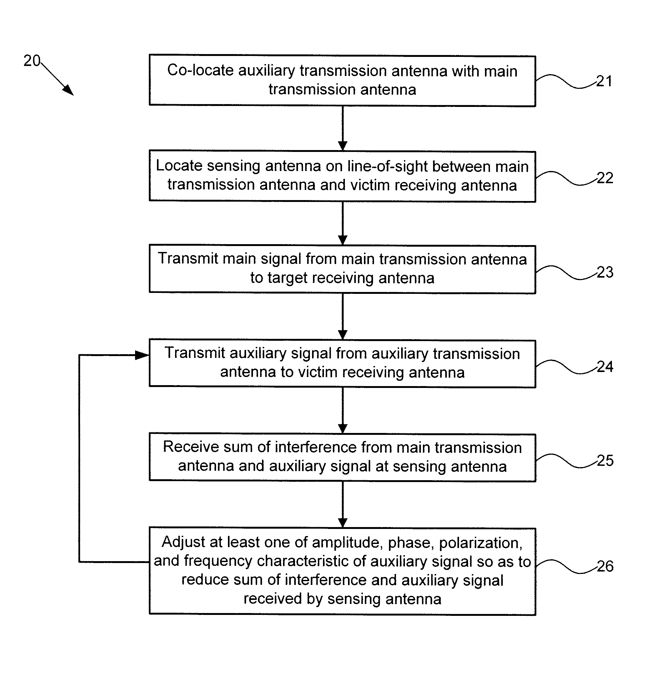
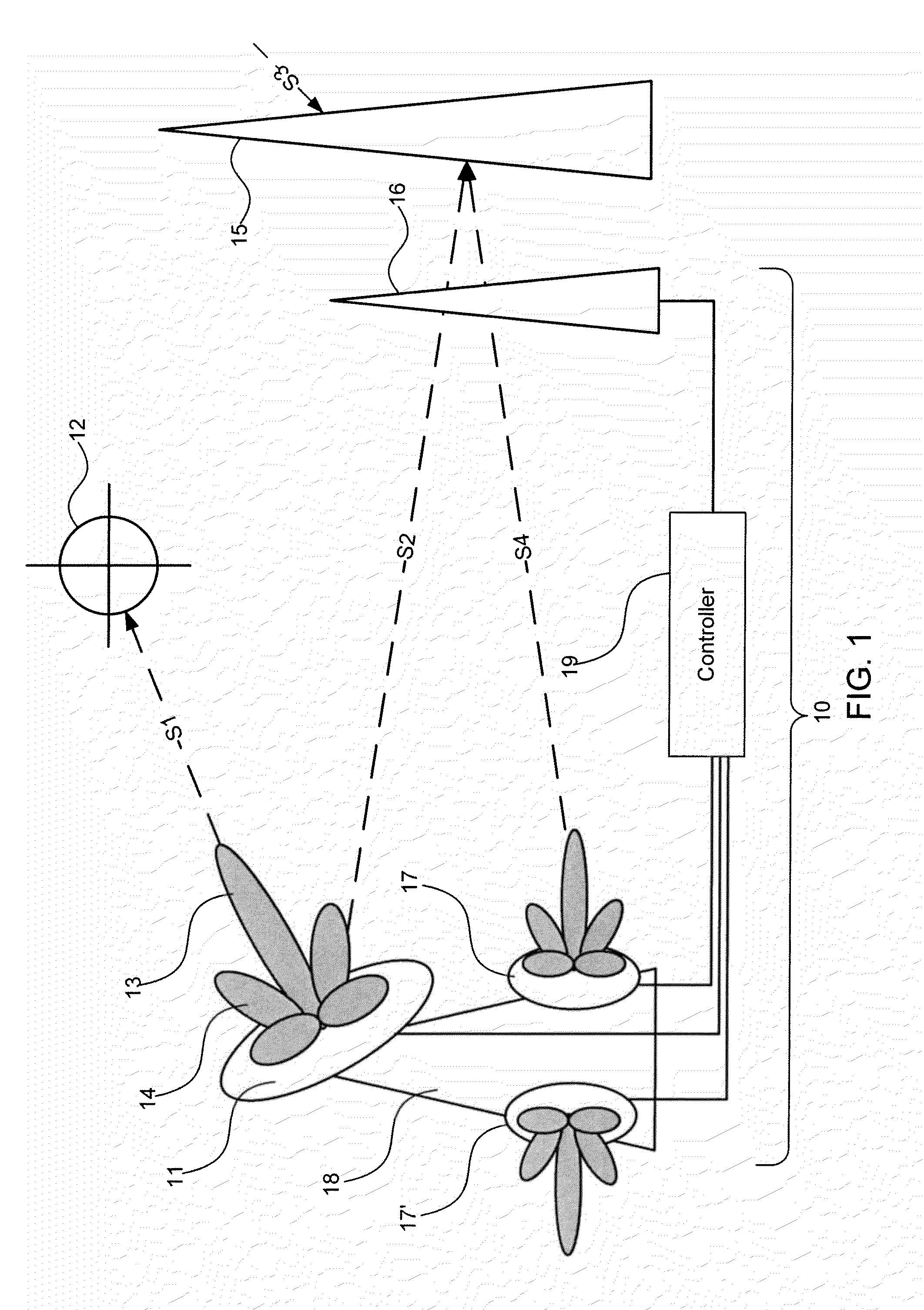
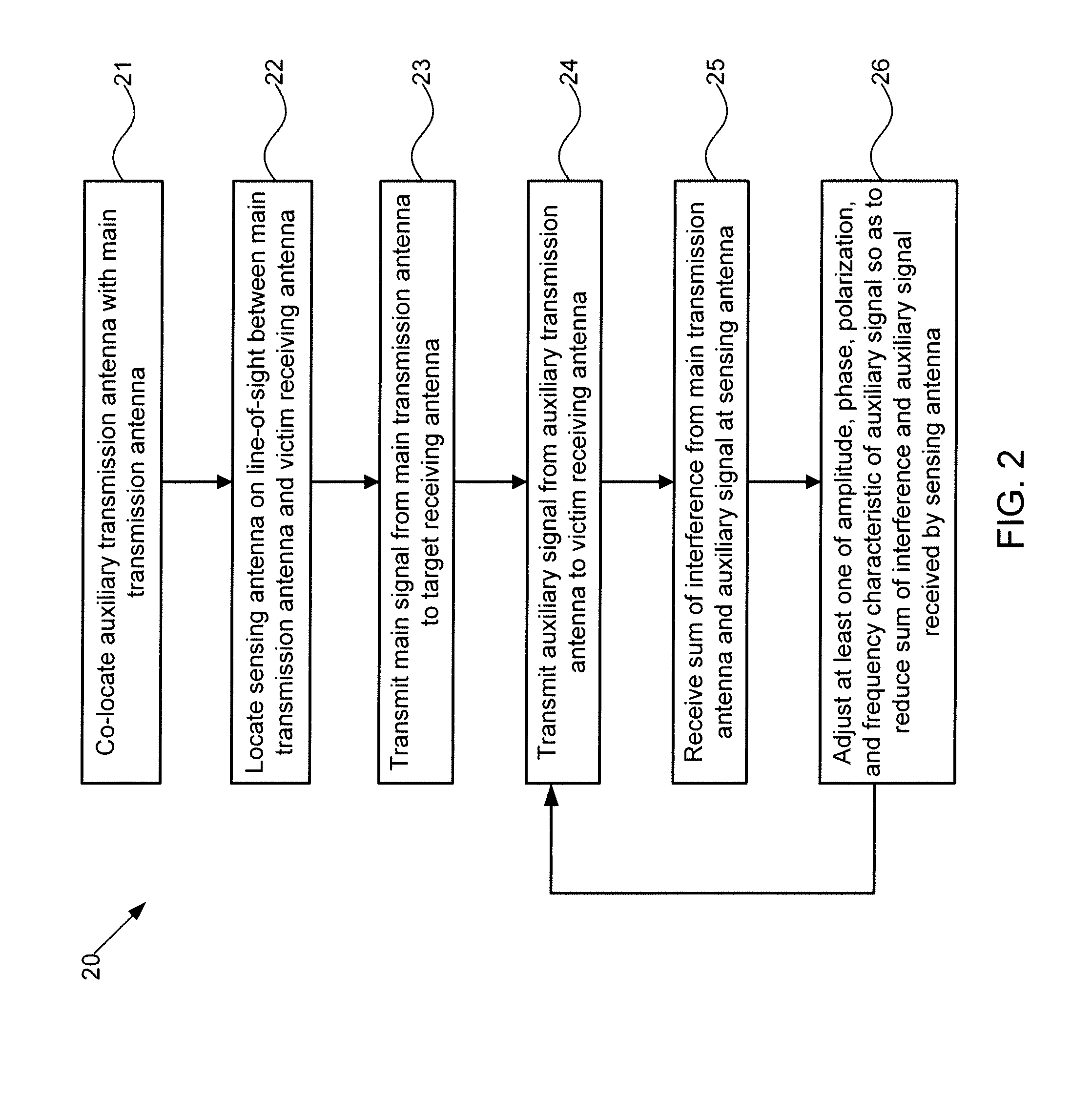
[0018]Embodiments of the present invention provide systems and methods for protecting a victim antenna from interference by a transmission antenna. As described in greater detail below, an auxiliary antenna is co-located with the transmission antenna, and a sensing antenna is located on the line-of-sight between the transmission and victim antennas. The sensing antenna is configured so as to receive approximately the same signals as does the victim antenna. As the transmission antenna transmits a signal to a target, the sensing antenna receives approximately the same amplitude, phase, polarization, and frequency content of interference as does the victim antenna. Based on the interference received by the sensing antenna, the auxiliary antenna generates a signal that reduces or cancels that interference, without significantly impairing the main signal transmitted from the transmission antenna to its target. Coordination between the sensing and auxiliary antennas may be achiev...


PUM


Abstract

Embodiments of the invention provide systems and methods for systems and methods for adaptively canceling interfering signals generated by a transmission antenna. Under one aspect, a system includes: an auxiliary antenna co-located with the main antenna, the auxiliary antenna configured to transmit an auxiliary signal to the victim antenna; a sensing antenna located on a line-of-sight path between the transmission antenna and the victim antenna, the sensing antenna configured to receive a composite of the interference and the auxiliary signal, and to output a first signal based on the received composite; a controller comprising an input coupled to the sensing antenna and configured to receive the first signal, the controller being configured to adjust at least one of an amplitude, a phase, a polarization, and a frequency characteristic of the auxiliary signal based on the first signal so as to reduce the composite of the interference and the auxiliary signal received by the sensing antenna.

Description

STATEMENT OF GOVERNMENT INTEREST[0001]This invention was made with government support under Contract No. FA8802-09-C-0001 awarded by the United States Air Force. The government has certain rights in the invention.FIELD OF THE INVENTION[0002]This application generally relates to systems and methods for reducing interference caused by a transmitting antenna in a nearby receiving antenna.BACKGROUND[0003]A signal generated by a transmitting antenna may cause interference for a nearby receiving antenna, i.e., a so-called “victim” antenna, which may inhibit the victim's ability to receive signals. Specifically, when a transmission antenna is configured to transmit a main signal to a target antenna, sidelobes of the main signal may extend in a variety of directions, and in particular, in the direction of the victim. The signal received by the victim antenna depends on the transmitted power level, the gain of the sidelobe level of the transmission antenna, the separation between the transmi...

Claims


Application Information

Patent Timeline
Patent Type & Authority Patents(United States)
IPC IPC(8): G01S3/16G01S3/28
CPCG01S7/2813H04B7/0825H04B7/0842
Inventor DYBDAL, ROBERT B.SOOHOO, KEITH M.CURRY, SAMUEL J.
Owner THE AEROSPACE CORPORATION
Why Eureka
Try Eureka