Image encoding apparatus using packet transmission order rearrangement and operating method thereof

A technology of rearrangement and image encoding, applied in the direction of digital transmission system, encoding, transmission system, etc., can solve the problems of data packet loss, multiple data packet loss, image destruction, etc., and achieve the effect of reducing usage and data packet loss.

Inactive Publication Date: 2019-07-05
欧鹏斯泰克公司
View PDF6 Cites 4 Cited by
  • Summary
  • Abstract
  • Description
  • Claims
  • Application Information

AI Technical Summary

Problems solved by technology

[0006] In the existing one-to-M transmission and reception structure, the transmitter can transmit images in packet units, but packet loss may occur due to higher image quality or higher capacity, network load or congestion.
In addition, the loss of data packets can lead to image corruption or interruption of image flow, and the lost data packets are difficult to recover, etc.
[0007] For example, a number of data packets sent by an existing sender do not reach the destination normally, but some of the data packets are lost on the router

Method used


Image

  • Image encoding apparatus using packet transmission order rearrangement and operating method thereof
  • Image encoding apparatus using packet transmission order rearrangement and operating method thereof
  • Image encoding apparatus using packet transmission order rearrangement and operating method thereof

Examples


Embodiment Construction

[0031] Embodiments of the present invention will be described in detail below with reference to the drawings and the contents described in the drawings, but the present invention is not limited to these embodiments.

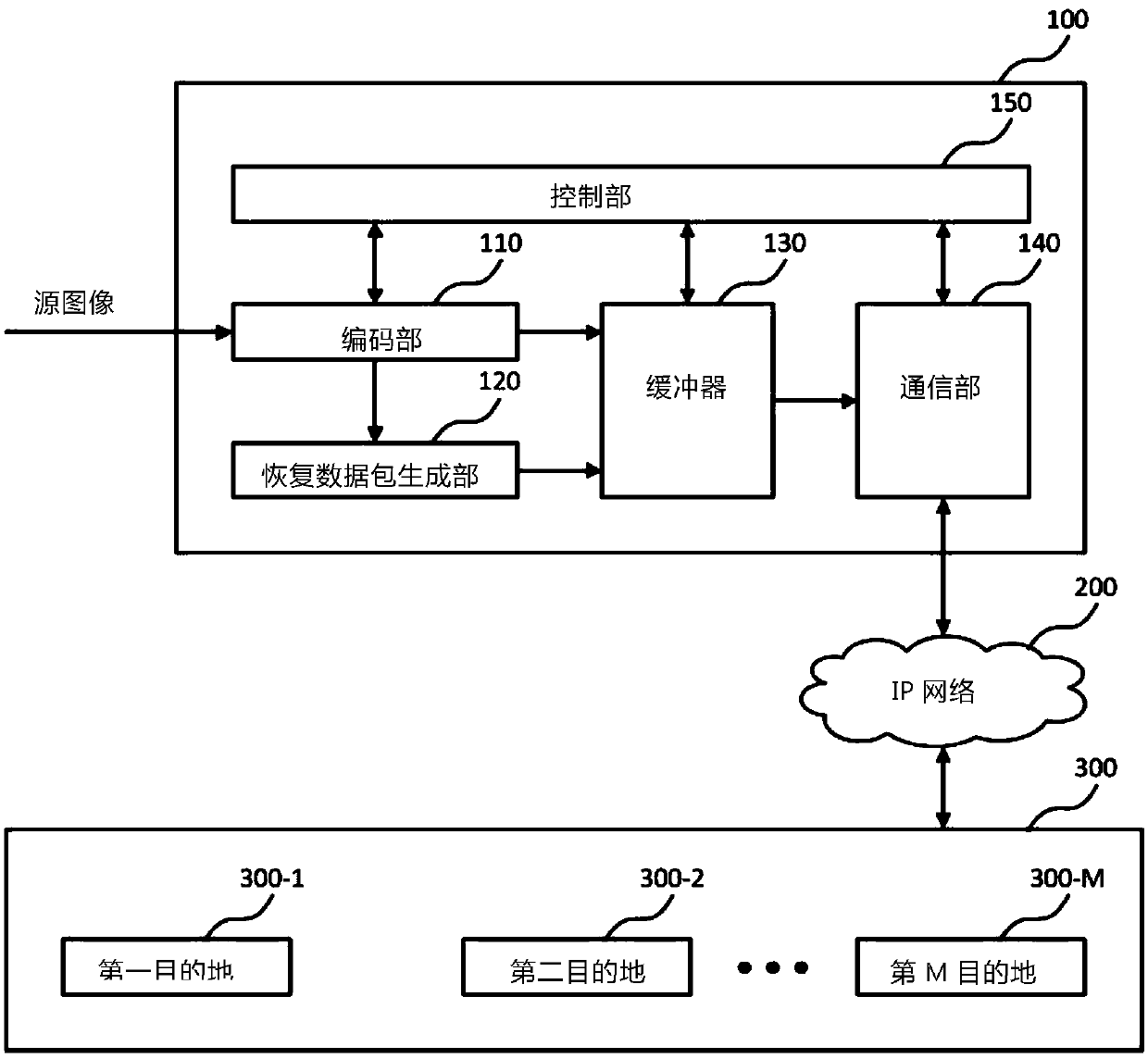
[0032] figure 1 is a block diagram illustrating an image encoding device of an embodiment of the present invention, and the image encoding device (100) can communicate with M destinations.

[0033] An image encoding device (100) includes: an encoding unit (110), a restored data packet generating unit (120), a buffer (130), a communication unit (140), and a control unit (150).

[0034] The encoding unit (110) encodes the source image to generate a source data packet, the restoration data packet generation unit (120) generates a restoration data packet for restoring the source data packet, and the buffer (130) temporarily stores the source data packet and the restoration data packet The communication part (140) sequentially transmits the source data packets and re...


PUM


Abstract

The present invention discloses an image encoding apparatus using a packet transmission order rearrangement and an operating method thereof, capable of reducing a loss of packets due to network congestion by rearranging the packets arranged with the form of an A_i,j matrix into the form of a B_k matrix by adjusting a transmission order according to a destination based on the total number of packets according to the destination or using only a header pointer corresponding to the number of destinations and the arrangement of a one-dimensional matrix.

Description

[0001] 【Technical field】 [0002] The present invention relates to a technique of sending different numbers of recovery data packets to each destination based on the data packet loss ratio of each destination. [0003] 【Background technique】 [0004] The patent document (Korean Registered Patent No. 10-1240895) relates to a UWB (Ultra Wide Band)-based communication system including a transmitter and a plurality of receivers. A transmitter generates a data packet and transmits the generated data packet to a plurality of receivers. receiver. [0005] In the existing communication system, the sender can encode the same image and then send the data packet to multiple receivers in real time. After the multiple receivers decode the data packet, the image is transmitted to the peripheral device or played. For example, if the sender is located in Seoul, the sender can send the same image to receivers in multiple destinations in Korea such as Incheon, Daejeon, Gwangju, Daegu, and Busan...

Claims


Application Information

Patent Timeline
Patent Type & Authority Applications(China)
IPC IPC(8): H04N19/154H04N19/426H04N19/70
CPCH04N19/154H04N19/426H04N19/70H04L65/80H04N21/64738H04N21/631H03M13/3761H04L1/0071H04L2001/0093H04L1/0041H04L43/0829H04L65/762H04L65/70H04N19/164H04N19/85H04L47/54H04L49/9057H04L1/1621H04L47/12H04L1/1835H04L1/0009
Inventor 南在权崔镐珍李宣旼姜信赫柳赞赫阮红泉
Owner 欧鹏斯泰克公司
Why Eureka
Try Eureka