Row bar with smart sensor for forming sliders and method of manufacturing slider

a smart sensor and slider technology, applied in the direction of maintaining head carrier alignment, magnetic bodies, instruments, etc., can solve the problems of insufficient accuracy and limited use of elg, and achieve the effect of greatly improving the performance of sliders and accurate control of form

Active Publication Date: 2013-12-24
SAE MAGNETICS (HK) LTD
View PDF4 Cites 3 Cited by
  • Summary
  • Abstract
  • Description
  • Claims
  • Application Information

AI Technical Summary

Benefits of technology

[0009]One objective of the present invention is to provide a row bar with smart sensor for forming sliders, the row bar having main poles and at least one smart sensor composed of a plurality of dummy poles disposed therein, with the dummy pole structure being identical to that of said main pole; there is a spaces between every two adjacent dummy poles of said smart sensor, and there is a offset in the direction vertical with the pole face between every two adjacent dummy poles. Therefore, the shape of the final pole surface of the main pole could be accurately controlled to form with the guide of the smart sensor during the lapping process, whereby the performance of the slider is greatly improved.
[0010]Another objective of the present invention is to provide a method of manufacturing slider cut from a row bar, the row bar having main poles and at least one smart sensor composed of a plurality of dummy poles disposed therein, with the dummy pole structure being identical to that of said main pole; there is a the space between every two adjacent dummy poles of said smart sensor, and there is a offset in the direction vertical with the pole face between every two adjacent dummy poles. Therefore, the shape of the final pole surface of the main pole could be accurately controlled to form with the guide of the smart sensor during the lapping process, whereby the performance of the slider is greatly improved.
[0025]In comparison with the prior art, the row bar has main poles and at least one smart sensor composed of a plurality of dummy poles disposed therein, with the dummy pole structure being identical to that of said main pole; there is a space between every two adjacent dummy poles of said smart sensor, and there is a offset in the direction vertical with the pole face between every two adjacent dummy poles. Therefore, the shape of the final pole surface of the main pole could be accurately controlled to form with the guide of the smart sensor during the lapping process, whereby the performance of the slider is greatly improved.

Problems solved by technology

However, the using of the ELG is such limited for lapping process.
Furthermore, because testing the lapping surface of the regular triangle and the inverted triangle while being lapped is not available, the lapping process is just based on the experience of the skilled to determinate the terminated time, so it could not be accurate enough.

Method used


Image

  • Row bar with smart sensor for forming sliders and method of manufacturing slider
  • Row bar with smart sensor for forming sliders and method of manufacturing slider
  • Row bar with smart sensor for forming sliders and method of manufacturing slider

Examples


Embodiment Construction

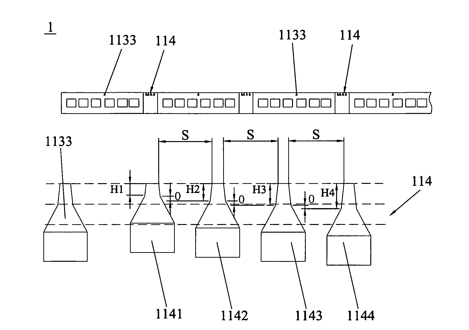
[0040]Various preferred embodiments of the invention will now be described with reference to the figures, wherein like reference numerals designate similar parts throughout the various views. As indicated above, the invention is directed to row bar for forming sliders, the row bar having main poles and at least one smart sensor composed of a plurality of dummy poles disposed therein, with the dummy pole structure being identical to that of said main pole; the spaces between every two adjacent dummy poles of said smart sensor are identical, and there is a offset in the direction vertical with the pole face between every two adjacent dummy poles. Therefore, the shape of the final pole surface of the main pole could be accurately controlled to form with the guide of the smart sensor during the lapping process, whereby the performance of the slider is greatly improved.

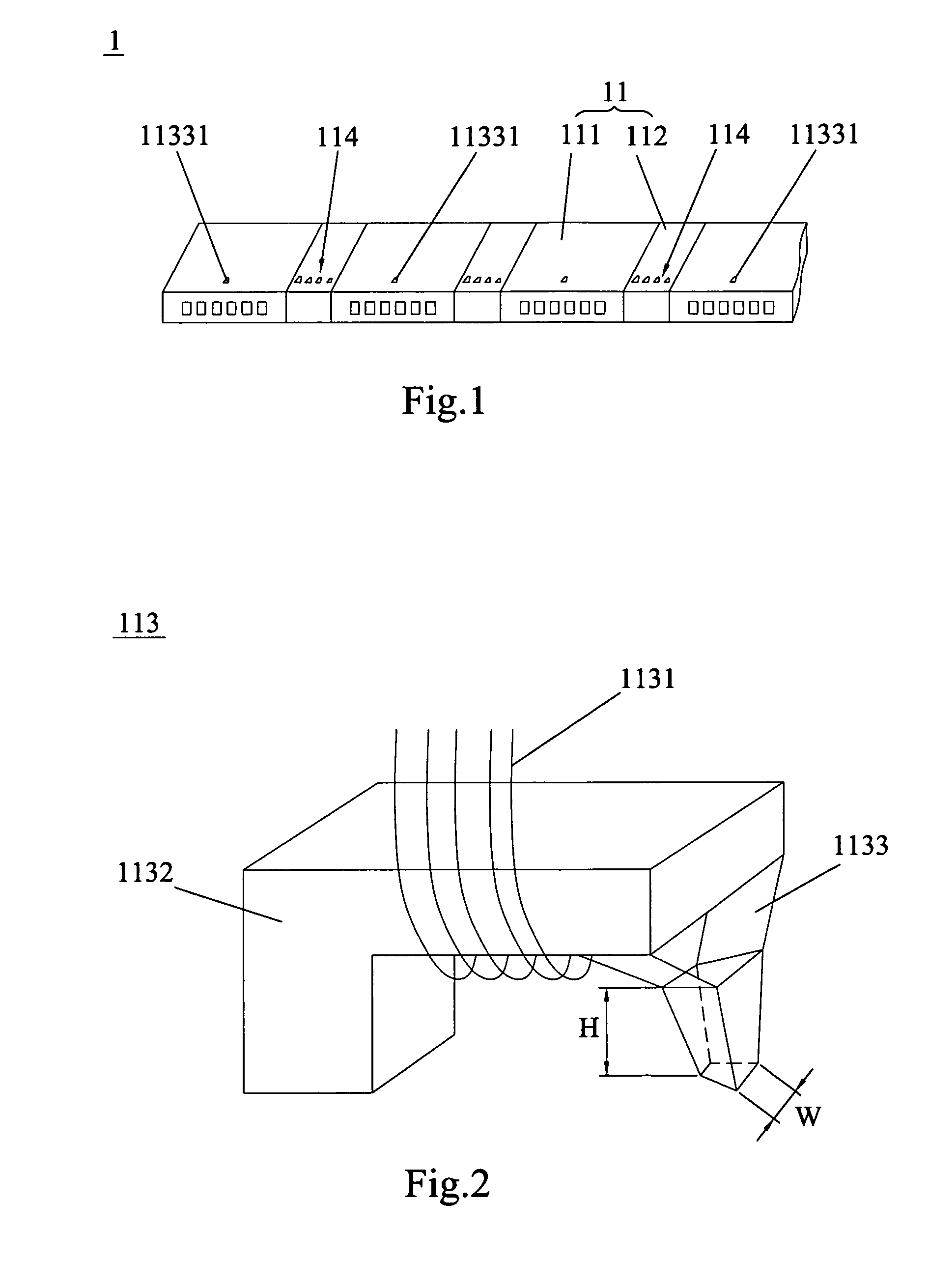
[0041]FIG. 1 demonstrates a row bar according to the first embodiment of the invention. As known in the art, a row bar w...


PUM

PropertyMeasurementUnit
widthaaaaaaaaaa
heightaaaaaaaaaa
lapping heightaaaaaaaaaa

Abstract

A row bar with smart sensor for forming sliders, which comprises a row of slider forming portions, each slider forming portion comprising a slider to be cut from the row bar and a medial region adjacent the slider; each slider comprises a slider body and a magnetic writer disposed in the slider body, with the magnetic writer having a main pole which includes a pole face for being lapped, and all the main poles are arranged in a row; the row bar has at least one smart sensor disposed therein, with the smart sensor having at least three dummy poles, whose structure is identical to that of said main pole, arranged in the row of the main poles, there is a space between every two adjacent dummy poles of said smart sensor, and there is a offset in the direction vertical with the pole face between every two adjacent dummy poles of said smart sensor. The invention also discloses a method of manufacturing the slider.

Description

FIELD OF THE INVENTION[0001]This application claims priority to Chinese Application No. 201010201207.7 filed Jun. 3, 2010, the entire contents of which are hereby incorporated by reference in this application.[0002]The present invention relates to information recording disk drive devices, and more particularly, to a row bar with smart sensor for forming sliders and a method of manufacturing the slider.BACKGROUND OF THE INVENTION[0003]The recording systems of magnetic read / write devices include a longitudinal magnetic recording system wherein signals are magnetized in the direction along the surface of the recording medium (the longitudinal direction), and a perpendicular magnetic recording system wherein signals are magnetized in the direction perpendicular to the surface of the recording medium. It is known that the perpendicular magnetic recording system is harder to be influenced by thermal fluctuation of the recording medium and capable of implementing higher linear recording de...

Claims


Application Information

Patent Timeline
Patent Type & Authority Patents(United States)
IPC IPC(8): G11B5/60
CPCG11B5/3116G11B5/3169G11B5/3173Y10T29/4902Y10T29/53165
Inventor FUJII, RYUJILAU, WAIKEUNGLI, GUOWEIWANG, LONGPINGXIAO, XIANGBINWANG, QUANBAO
Owner SAE MAGNETICS (HK) LTD
Why Eureka
Try Eureka