Press molding method, manufacturing method for press-molded component, and method for determining preform shape for use in said methods

a manufacturing method and press molding technology, applied in the direction of transportation and packaging, vehicle components, etc., can solve the problems of increasing the mold cost, bringing about the increase of the mold cost, and difficulty in controlling the proper wrinkle-pressing for

Active Publication Date: 2016-12-08
JFE STEEL CORP
View PDF2 Cites 3 Cited by
  • Summary
  • Abstract
  • Description
  • Claims
  • Application Information

AI Technical Summary

Benefits of technology

[0026]Further, in the method for determining the preform shape according to the invention, a difference W−W0 between an inflow quantity W of the material from the position generating flange wrinkles and an inflow quantity W0 of the material from a flange portion generating no flange wrinkles adjacent to the position generating flange wrinkles is determined and the preforming bead shape may be set to

Problems solved by technology

In the technique disclosed in Patent Document 1, however, since the wrinkle-pressing mold is divided, the structure of the mold becomes complicated and hence the manufacturing cost of the mold is increased.
Also, the control of the proper wrinkle-pressing

Method used


Image

  • Press molding method, manufacturing method for press-molded component, and method for determining preform shape for use in said methods
  • Press molding method, manufacturing method for press-molded component, and method for determining preform shape for use in said methods
  • Press molding method, manufacturing method for press-molded component, and method for determining preform shape for use in said methods

Examples


example

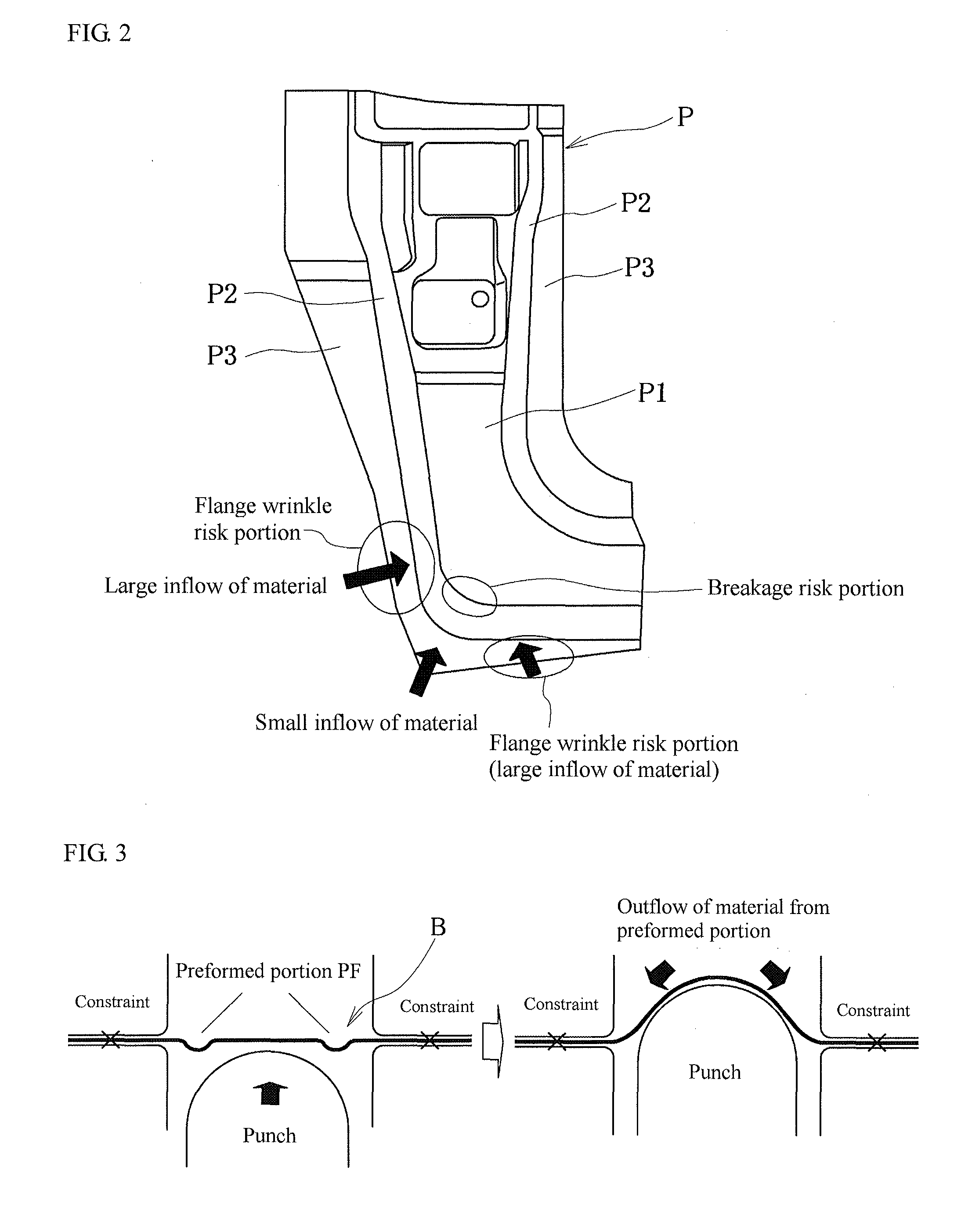
[0050]An example of the above embodiment and a comparative example will be described below. Assuming that a L-shaped component shape of a press-formed component P shown in FIG. 2 is used as a product shape, an FEM analysis is conducted in the drawing performed with a press mold comprised of an upper die and a lower mold provided with a punch cooperated with the upper die and a blank holder clipping a blank together with the upper die as shown in FIG. 4. As conditions of FEM analysis, a solver is a LD-DYNA version 971 (dynamic explicit method) and a mesh size is 2 mm. A blank material is a steel sheet of 1180 MPa grade with a thickness of 1.6 mm, and a stress-strain relation approximated by Swift equation of stress-strain curve measured from JIS No. 5 specimen for tensile test. A frictional coefficient between the blank and the mold is 0.12. A cushion force (wrinkle-pressing force) is 50 tons and 80 tons. The judgement of breakage risking portion and flange wrinkle risking portion sh...


PUM

PropertyMeasurementUnit
Shapeaaaaaaaaaa
Strain pointaaaaaaaaaa
Distributionaaaaaaaaaa

Abstract

A method is provided for press forming a product having a shape of a top board portion, a vertical wall portion continuously formed from the top board portion and a flange portion continuously formed from the vertical wall portion at a press process of two or more stages, wherein a convex or concave bead shape is preformed in a position of a flat metal sheet as a raw material corresponding to a neighborhood of a position generating breakage or flange wrinkles when the raw material is formed into a product shape, and thereafter a product shape is press formed from the raw material having the preformed bead shape.

Description

CROSS-REFERENCE TO RELATED APPLICATIONS[0001]This is the U.S. National Phase application of PCT International Application No. PCT / JP2015 / 051958, filed Jan. 26, 2015, and claims priority to Japanese Patent Application No. 2014-012949, filed Jan. 28, 2014, the disclosures of each of these applications being incorporated herein by reference in their entireties for all purposes.FIELD OF THE INVENTION[0002]This invention relates to a press forming method comprising a pressing process of two or more stages and a method for producing a press-formed component as well as a method for determining a preform shape formed prior to a final step in the press forming.BACKGROUND OF THE INVENTION[0003]In order to attain weight saving of an automobile and improvement of collision safety, it is promoted to increase a strength of a steel sheet used in automobile components. Most of automobile components are manufactured by press forming as a press-formed part being one of press products. However, they h...

Claims


Application Information

Patent Timeline
IPC IPC(8): B21D22/02
CPCB21D22/02B21D22/26B21D53/88B21D22/22B21D24/04
Inventor SHINMIYA, TOYOHISASHIOZAKI, TSUYOSHIIIZUKA, EIJIYAMASAKI, YUJI
Owner JFE STEEL CORP
Why Eureka
Try Eureka