Seamlessly embedded heart rate monitor

a heart rate monitor and seamless technology, applied in the field of seamless heart rate monitors, can solve the problems of not being aesthetically pleasing and disabling authentication features, and achieve the effects of avoiding shorting or interference, retaining aesthetic appeal and appearance of electronic devices, and sufficient conductivity

Active Publication Date: 2013-12-24
APPLE INC
View PDF13 Cites 121 Cited by
  • Summary
  • Abstract
  • Description
  • Claims
  • Application Information

AI Technical Summary

Benefits of technology

[0011]In some embodiments, if the electrical conductivity of portions of the electronic device enclosure and the leads are suitably selected and designed, the leads can be positioned underneath the exterior surface of the enclosure while providing sufficient conductivity for detecting cardiac electrical signals and avoiding shorting or interference between adjacent leads. For example, the sensor leads can be constructed from a silver based compound having high electrical conductivity, while the electronic device enclosure can be constructed from steel and aluminum, both having lower electrical conductivity. By placing several leads at substantially larger distances apart along the electronic device enclosure than the thickness of the enclosure, electronic signals can be transmitted through the steel or aluminum enclosure to a silver based lead underneath the enclosure, but not along the surface of the enclosure to cause adjacent leads to short.

Problems solved by technology

Although the leads can simply be placed on the exterior surface of the device housing, for example in a defined location where the user may place a finger, this approach is not aesthetically pleasing, and may cause some prospective buyers to consider other devices.
This additional step may in fact be so encumbering that users disable the authentication feature and instead use an unsecured electronic device.

Method used


Image

  • Seamlessly embedded heart rate monitor
  • Seamlessly embedded heart rate monitor
  • Seamlessly embedded heart rate monitor

Examples


Embodiment Construction

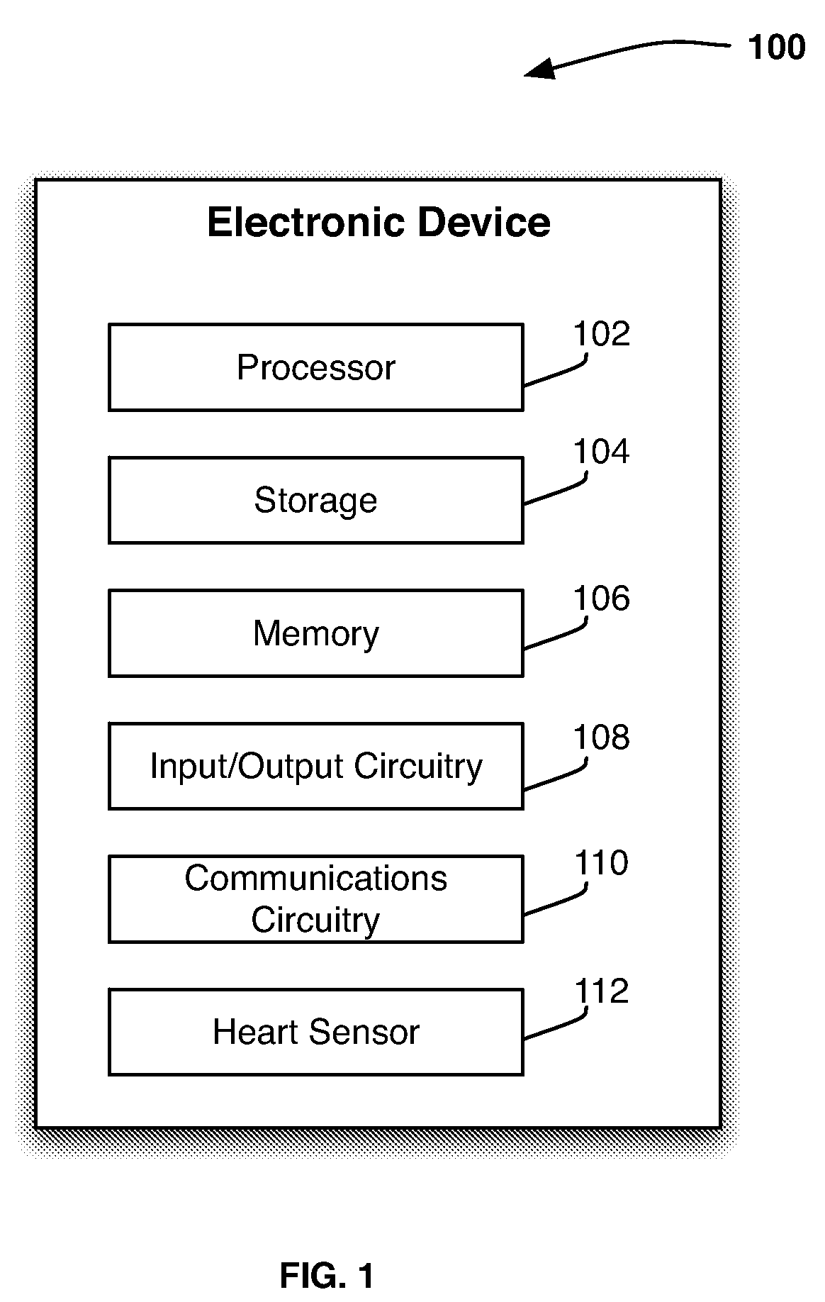
[0020]FIG. 1 is a schematic view of an illustrative electronic device for receiving the output of one or more sensors in accordance with one embodiment of the invention. Electronic device 100 can include control circuitry 102, storage 104, memory 106, input / output circuitry 108, communications circuitry 110, and heart sensor 112. In some embodiments, one or more of electronic device components 100 can be combined or omitted (e.g., combine storage 104 and memory 106). In some embodiments, electronic device 100 can include other components not combined or included in those shown in FIG. 1 (e.g., motion detection components, a power supply such as a battery or kinetics, a display, bus, or input mechanism), or several instances of the components shown in FIG. 1. For the sake of simplicity, only one of each of the components is shown in FIG. 1.

[0021]Control circuitry 102 can include any processing circuitry or processor operative to control the operations and performance of electronic de...


PUM


Abstract

This is directed to an electronic device having an integrated sensor for detecting a user's cardiac activity and cardiac electrical signals. The electronic device can include a heart sensor having several leads for detecting a user's cardiac signals. The leads can be coupled to interior surfaces of the electronic device housing to hide the sensor from view, such that electrical signals generated by the user can be transmitted from the user's skin through the electronic device housing to the leads. In some embodiments, the leads can be coupled to pads placed on the exterior of the housing. The pads and housing can be finished to ensure that the pads are not visibly or haptically distinguishable on the device, thus improving the aesthetic qualities of the device. Using the detected signals, the electronic device can identify or authenticate the user and perform an operation based on the identity of the user. In some embodiments, the electronic device can determine the user's mood from the cardiac signals and provide data related to the user's mood.

Description

CROSS-REFERENCE TO RELATED APPLICATION[0001]This application claims priority to U.S. Provisional Application No. 61 / 111,498, filed Nov. 5, 2008, which is incorporated by reference herein in its entirety.BACKGROUND OF THE INVENTION[0002]This is directed to providing a seamless heart-rate monitor in an electronic device.[0003]Many electronic devices are used to store personal or confidential information. In particular, portable electronic devices such as cellular telephones, personal assistants, and music players are often used to store or access e-mail, contact lists, communications history, remotely accessed accounts (e.g., telephone, banking or credit card accounts), or other information that a user may regard as personal or private. In addition, several users may use the same electronic device. For example, several users in a household may use the same computer or portable music player. As another example, a user may lend an electronic device to a friend (e.g., lend an iPod, avail...

Claims


Application Information

Patent Timeline
Patent Type & Authority Patents(United States)
IPC IPC(8): A61B5/0402A61B5/332
CPCA61B5/02438A61B5/0245A61B5/0404A61B5/04012A61B5/04085A61B5/044A61B5/117A61B5/6898A61B2560/0468A61B5/332A61B5/316A61B5/282A61B5/339
Inventor LIN, GLORIANAKAJIMA, TAIDORAHUL, PAREETHODGE, ANDREW
Owner APPLE INC
Why Eureka
Try Eureka