Safety gate

a safety gate and gate body technology, applied in the field of safety gates, can solve the problem of only slightly compressed resilience elemen

Active Publication Date: 2013-12-31
WANG TSUNG HSIANG
View PDF12 Cites 32 Cited by
  • Summary
  • Abstract
  • Description
  • Claims
  • Application Information

AI Technical Summary

Benefits of technology

[0008]The main objective of the present invention is to provide a safety gate that can be closed automatically when the safety gate is open slightly at a small angle.
[0010]When the fence door is open at an angle under 5 degrees relative to the doorframe, one of the guiding surfaces of the repositioning unit abuts a side of the top of the base frame. Because the guiding surface is curved and inclined relative to the fence door and because the distance between the two guiding surfaces is decreased gradually along the direction from the first side frame to the second side frame, the guiding surface gradually rotates the fence door to the doorframe. The fence door is rotated to close and is locked with the doorframe. As a result, the repositioning unit can close the fence door that is open slightly at a small angle.

Problems solved by technology

However, when the fence door of the conventional safety gate is open at a small angle, the resilient element is only slightly compressed.

Method used


Image

  • Safety gate
  • Safety gate
  • Safety gate

Examples


first embodiment

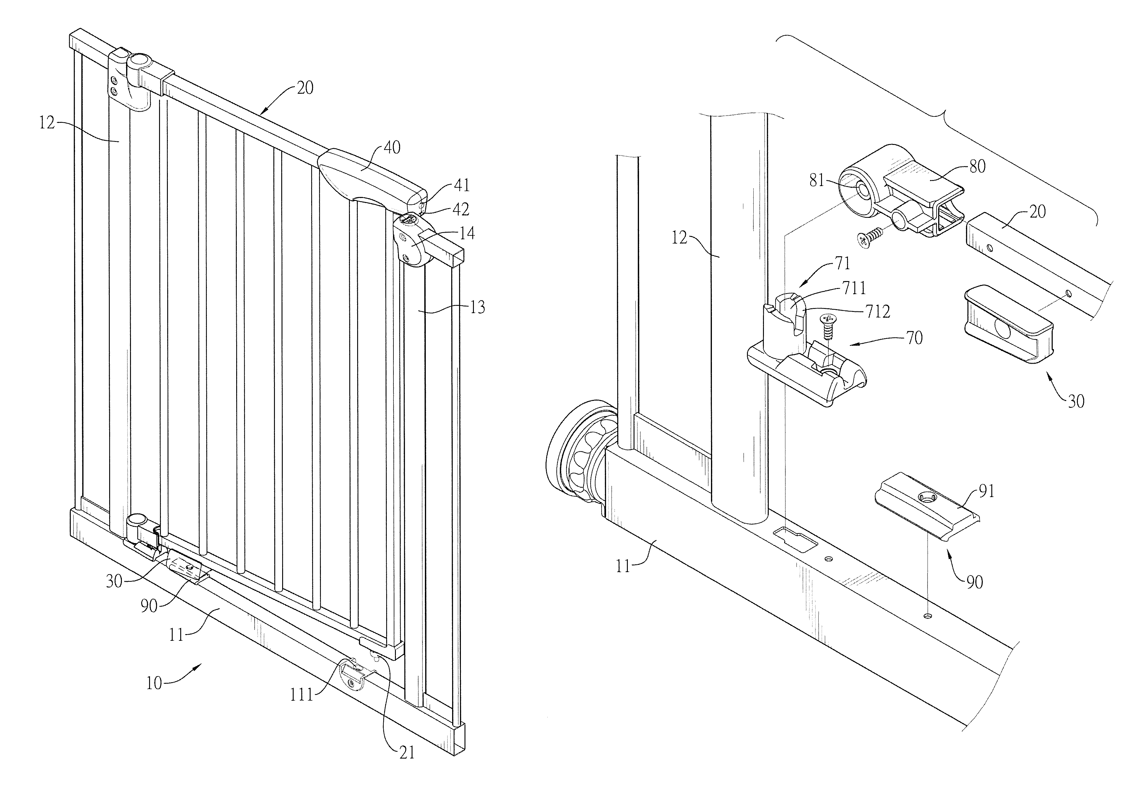
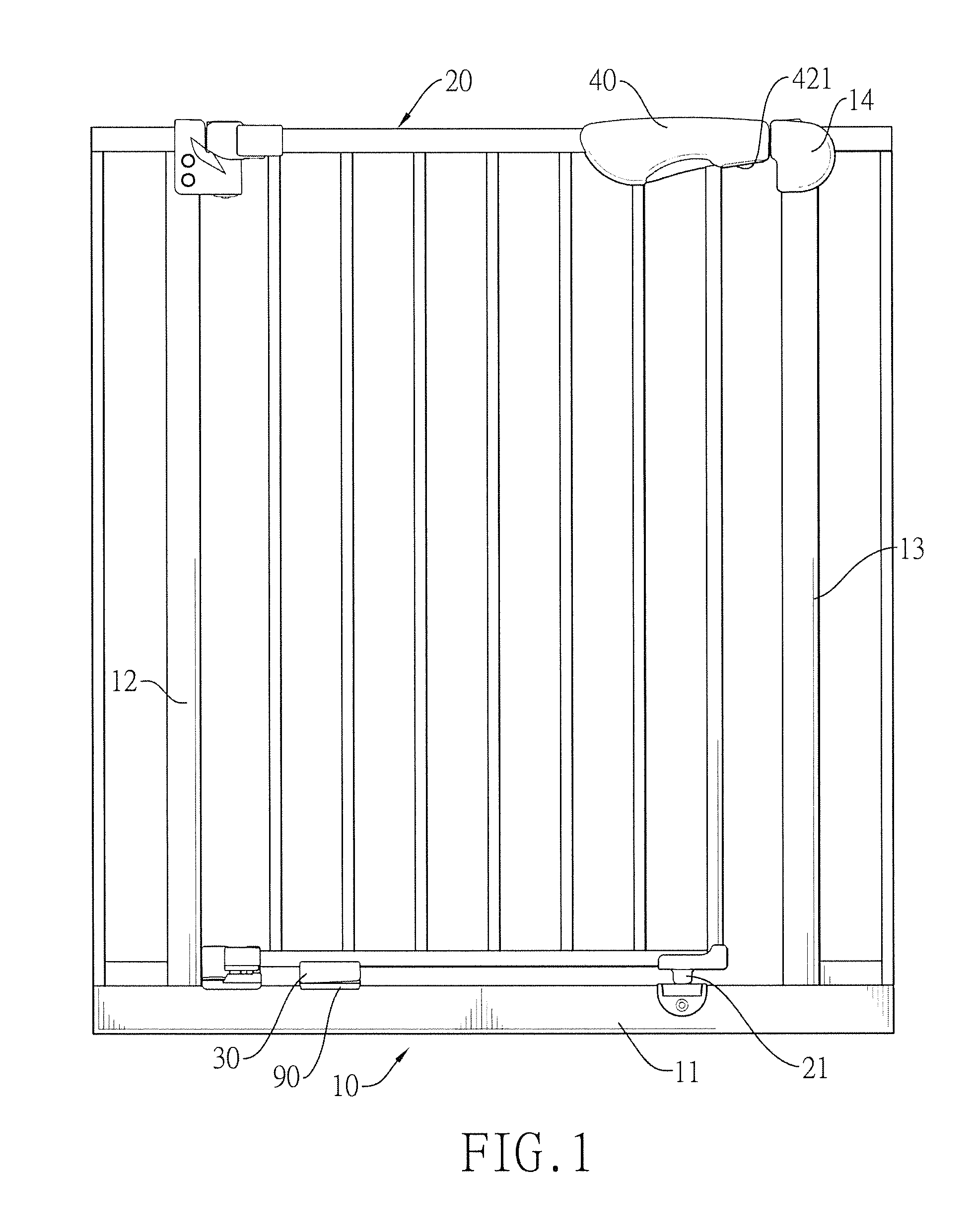
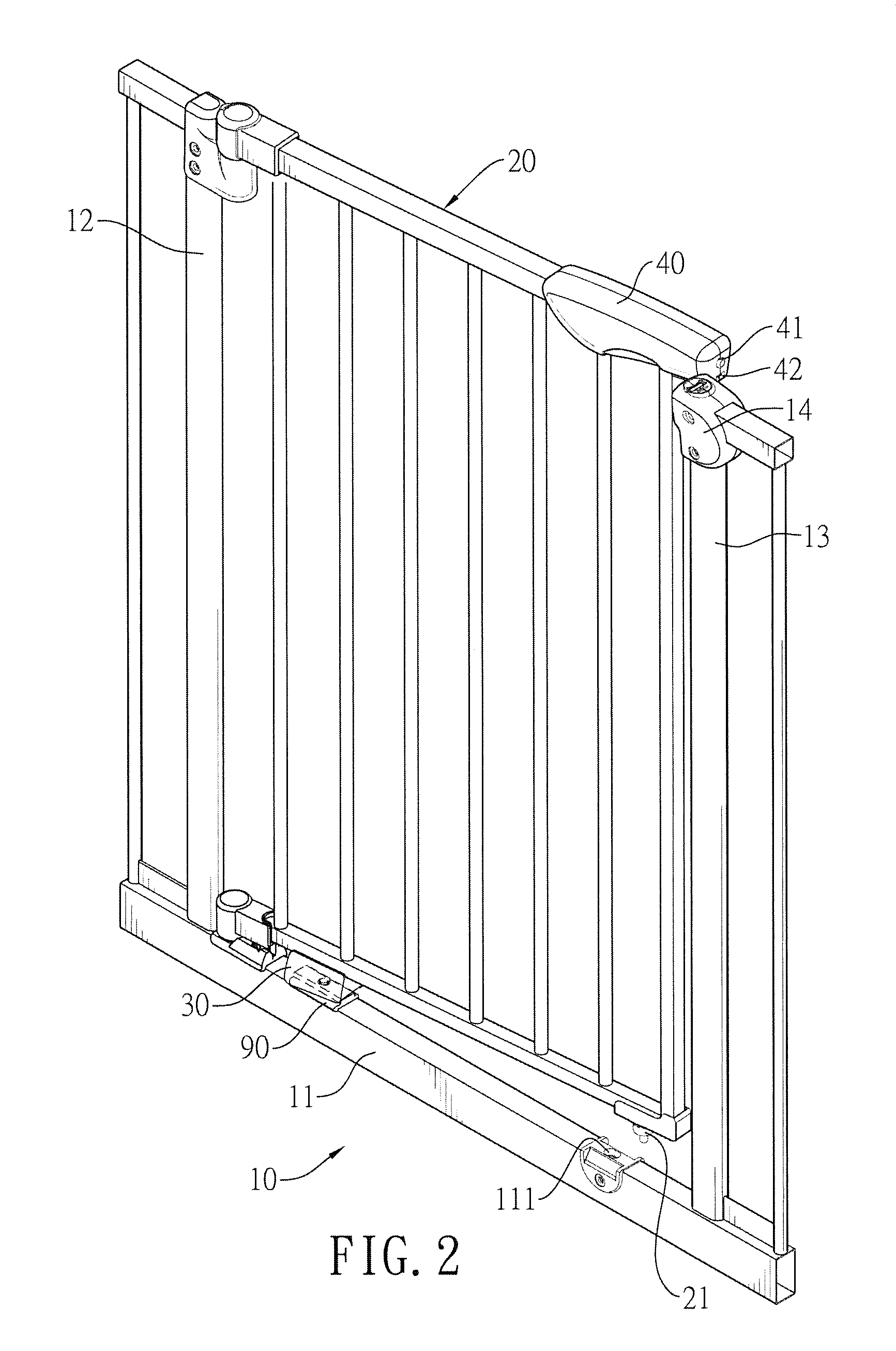
[0033]With reference to FIGS. 1 and 2, a safety gate in accordance with the present invention comprises a doorframe 10, a fence door 20, a repositioning unit 30 and a repositioning seat 90.

[0034]The doorframe 10 has a base frame 11, a first side frame 12 and a second side frame 13. The base frame 11 has two ends. The first side frame 12 is vertically mounted on one of the ends of the base frame 11. The second side frame 13 is vertically mounted on the other one of the ends of the base frame 11. A gate opening is formed between the side frames 12, 13. In a preferred embodiment, the base frame 11 has a lock recess 111 disposed in a top of the base frame 11 and adjacent to the second side frame 13.

[0035]The fence door 20 has a first side and a second side. The first side is rotatably connected to the first side frame 12 in an axially moveable manner. The second side is opposite to the first side. The fence door 20 is rectangular. A width of the fence door 20 corresponds to a width betw...

second embodiment

[0049]With reference to FIG. 16, the second embodiment has no lower pivot seat and no lower pivot unit and has an ordinary pivot device in replacement of the lower pivot seat and the lower pivot unit. The ordinary pivot device also allows the fence door 20A to rotate and axially move relative to the first side frame 12A.

[0050]With reference to FIGS. 13 to 15, the upper pivot seat 50A has two upper inclines 512A to replace the lower inclines of the lower pivot seat of the first embodiment. The upper pivot unit 60A has two upper ribs 64A to replace the lower ribs of the lower pivot unit of the first embodiment. Thus, besides the upper resilient element 63A, the upper pivot seat 50A and the upper pivot unit 60A also can rotate the fence door 20A during the course when the fence door 20A is moving down.

[0051]The second embodiment and the first embodiment have some difference in structure, but the second embodiment also can achieve the same function as the first embodiment.

[0052]With ref...


PUM


Abstract

A safety gate has a doorframe, a fence door and a repositioning unit. The doorframe has a base frame, a first side frame, and a second side frame. The repositioning unit is mounted on a bottom of the fence door and has a repositioning recess. The repositioning recess selectively engages a top of the base frame and has two opposite guiding surfaces. When the fence door is open at an angle under 5 degrees relative to the doorframe, one of the guiding surfaces abuts a side of the top of the base frame. Because the guiding surface is curved and inclined relative to the fence door and because a distance between the guiding surfaces is decreased gradually, the guiding surface gradually rotates the fence door to close. As a result, the repositioning unit can close the fence door that is open slightly at a small angle.

Description

BACKGROUND OF THE INVENTION[0001]1. Field of the Invention[0002]The present invention relates to a safety gate, especially to a safety gate that can be closed automatically when the safety gate is open slightly at a small angle.[0003]2. Description of the Prior Arts[0004]A safety gate is installed at an entrance to household areas that might be unsafe, such as kitchen, stairs, or bathrooms to keep babies or young children from entering. The safety gate has a doorframe and a fence door. The fence door is connected pivotally to the doorframe. The fence door can be pushed by a user to open or close the gate, and the fence door also can be locked with the doorframe such that the babies or young children cannot push the fence door open.[0005]A conventional safety door further has a resilient element mounted between the doorframe and the fence door. When the fence door is open, the resilient element is compressed. Then the compressed resilient element is extended by a resilient force and ...

Claims


Application Information

Patent Timeline
Patent Type & Authority Patents(United States)
IPC IPC(8): E05D15/06
CPCE04H17/00E06B9/04A47D13/00E06B2009/002E05F7/02E05Y2900/40E05Y2800/426E04H17/013
Inventor WANG, TSUNG-HSIANG
Owner WANG TSUNG HSIANG
Why Eureka
Try Eureka