Control panel assembly for laundry device and laundry device including the same

a technology for controlling panel assemblies and laundry devices, which is applied in the direction of coding, washing machines with receptacles, pulse techniques, etc., can solve the problems of inconvenience for modern people with busy daily lives, and achieve the effects of improving endurance of character parts, convenient button operation, and convenient mounting/dismounting

Inactive Publication Date: 2013-12-31
LG ELECTRONICS INC
View PDF38 Cites 11 Cited by
  • Summary
  • Abstract
  • Description
  • Claims
  • Application Information

AI Technical Summary

Benefits of technology

[0032]The plurality of buttons provided in a number the same number with a plurality of operation conditions permits user's easy operation of the buttons because what is required is to press the buttons only once for each time of operation.
[0033]The single button assembly having a plurality of buttons formed as one unit with a frame permits easy mounting / dismounting the button assembly to / from the control panel.
[0034]The character portions formed on a front of each buttons, or on outside surfaces of the control panel close to the buttons respectively by double injection molding improve endurance of the character portions, such that the character portions are not erased even if the character portions are brought into contact with a user's hand, frequently.
[0035]The position adjustment of the plurality of the buttons at the front of the control panel enables to form a good looking control panel.
[0036]The indicating units formed of a transparent material at a corner of each of the buttons for recognition of operation conditions of the laundry device by double injection molding permits user's easy recognition of the operation conditions and to improve endurance of the indication units.
[0037]The projection of the indicating unit from a front to a rear of the button, making a gap between the indicating unit and the LED lamp permits to minimize scattering of the light from the LED lamp and exposure of the light to an outside of the indicating unit.

Problems solved by technology

In general, though washed laundry is transferred to a drying rack for drying the laundry naturally, people of modern times who have busy daily lives experience inconvenience due to delay of the natural drying on a rainy season, or on unsettled days.

Method used


Image

  • Control panel assembly for laundry device and laundry device including the same
  • Control panel assembly for laundry device and laundry device including the same
  • Control panel assembly for laundry device and laundry device including the same

Examples


Embodiment Construction

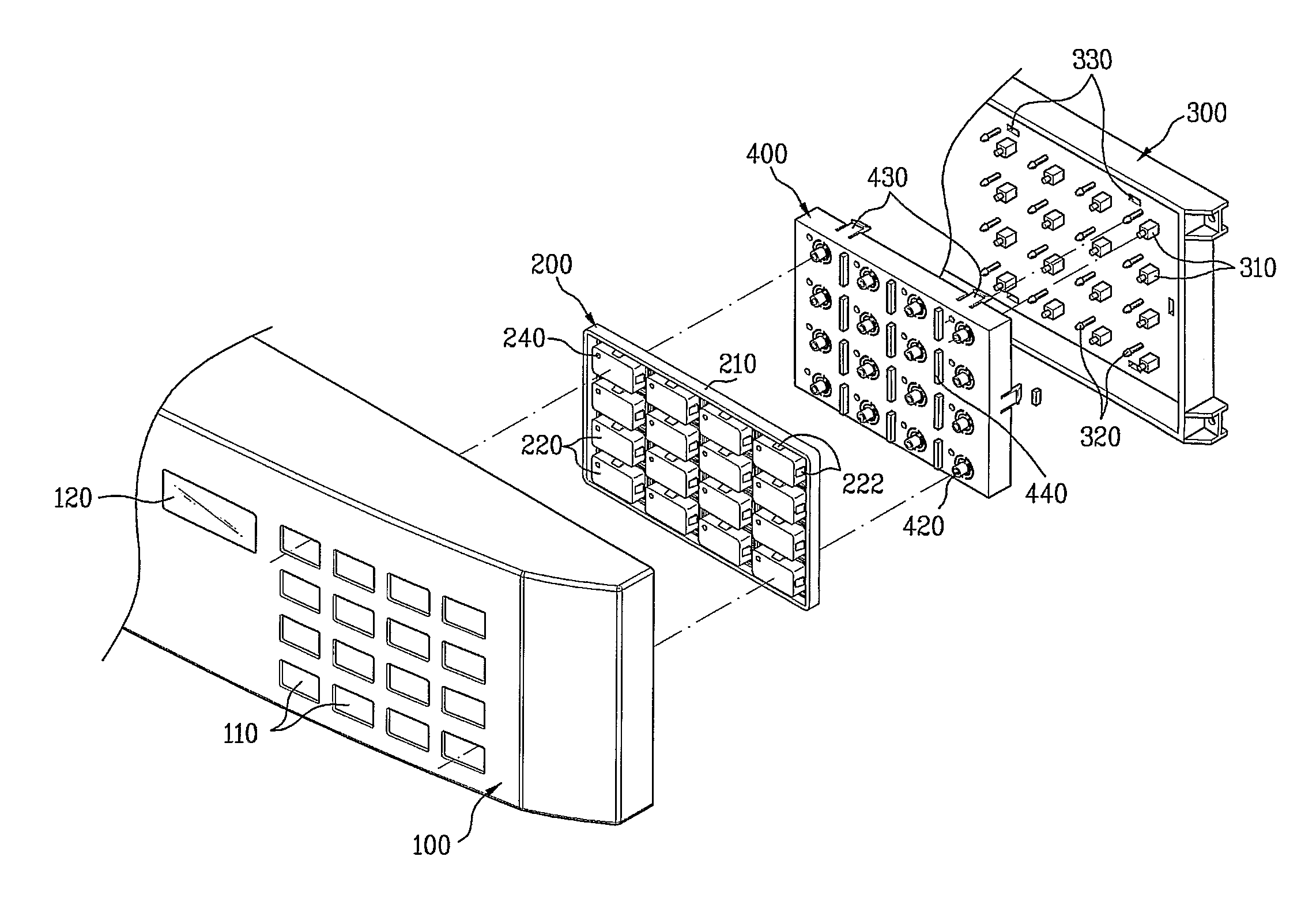
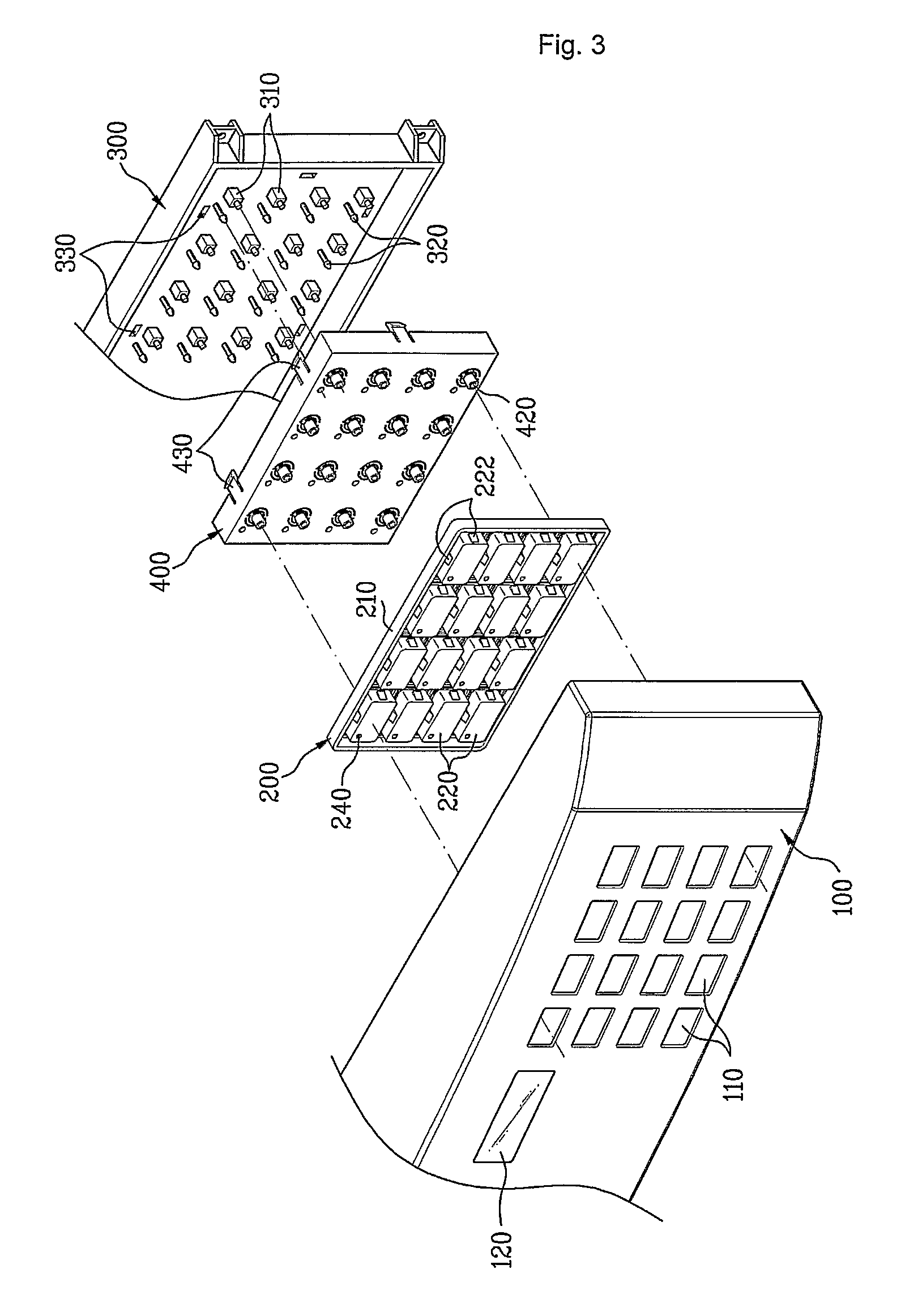
[0047]Reference will now be made in detail to the specific embodiments of the present invention, examples of which are illustrated in the accompanying drawings FIGS. 3 to 6.

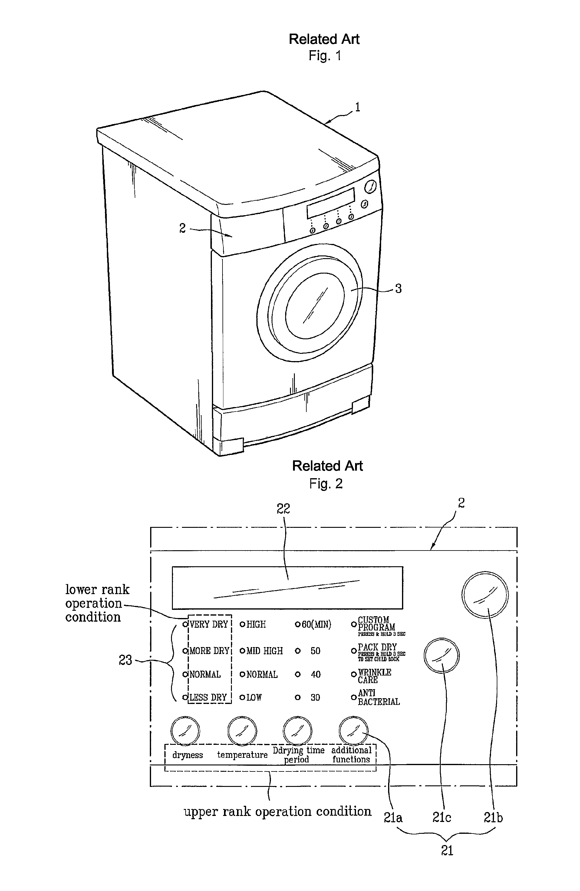
[0048]The present invention is applicable, not only to a dryer which dries laundry, but also to a washing machine which washes the laundry or a washing and drying machine. However, for convenience sake, the present invention will be described limited to the dryer taking as an example of the laundry device.

[0049]The control panel assembly of the present invention includes a control panel 100, a button assembly 200, a board guide 300, and a lamp supporter 400. Though it will be described later, by forming an element equivalent to the lamp supporter 400 on the button assembly 200 or the board guide 300, the lamp supporter 400 may be omitted.

[0050]The control panel 100 forms an exterior of the control panel assembly, and is detachably mounted to a front of the dryer. The control panel 100 has a plurality of mounting ...


PUM


Abstract

An improved control panel assembly is easy to fabricate, and easy to recognize a selected operation condition, and a laundry device with the same. The control panel assembly for a laundry device includes a button assembly having a plurality of buttons provided in correspondence to operation conditions, a control panel having a plurality of mounting holes for exposure of the plurality of buttons therethrough from a front thereof, and a frame on a rear of the control panel, the frame joining the plurality of buttons as one unit, and preventing pressing interference between adjacent buttons.

Description

TECHNICAL FIELD[0001]The present invention relates to control panel assemblies for laundry devices and laundry devices with the same. More specifically, the present invention relates to an improved control panel assembly which is easy to fabricate, and easy to recognize a selected operation condition, and a laundry device with the same.BACKGROUND ART[0002]The present invention relates to control panel assemblies for laundry devices and laundry devices with the same. More specifically, the present invention relates to an improved control panel assembly which is easy to fabricate, and easy to recognize a selected operation condition, and a laundry device with the same.[0003]In general, washing machines for washing and spinning laundry, dryers for drying the laundry, and washing and drying machines both for washing and drying are called as the laundry devices, collectively.[0004]The dryer is an appliance for heating dry air with heating means, blowing the dried air to a drum, for evapo...

Claims


Application Information

Patent Timeline
Patent Type & Authority Patents(United States)
IPC IPC(8): D06F35/00H01H9/00D06F29/00D06F39/00
CPCD06F39/005D06F34/30
Inventor YOON, JU HANHWANG, SUNG GIKIM, SEONG KYUHEO, SEON IL
Owner LG ELECTRONICS INC
Why Eureka
Try Eureka