Test device for testing flexible separators

a test device and flexible separator technology, applied in the direction of machine part testing, withdrawing sample devices, material strength testing using repeated/pulsating forces, etc., can solve the problem of limiting the rate at which deformation cycles can alternate, the duration of reliability tests for a large number of cycles is therefore very long, and the duration of testing is short. , the effect of simple and inexpensiv

Active Publication Date: 2013-12-31
OLAER INDS
View PDF3 Cites 0 Cited by
  • Summary
  • Abstract
  • Description
  • Claims
  • Application Information

AI Technical Summary

Benefits of technology

[0004]The method of the invention is designed, amongst other things, to avoid the need for a complex hydraulic circuit and to make it possible to accelerate the rate of cycling (4 hertz (Hz) to 6 Hz, instead of 1 Hz or 2 Hz), thereby significantly shortening the duration of testing while continuing testing until rupture of a separator. Furthermore, because of its “push-pull” mode of operation, the method of the invention gives rise to energy consumption that is well below that of the prior art system, as recalled above, and does so with a structure that is relatively simple and inexpensive.
[0006]The fact of using pressure that is low but substantially in the same liquid / gas compression ratio, gives rise to comparable amounts of separator deformation while allowing deformation cycles to be performed at a high rate (a few hertz), thereby enabling the lifetime of the separator as such to be better evaluated by running tests until separator rupture in lengths of time that are shorter and acceptable, given industrial constraints. The invention enables this object to be achieved.
[0010]The arrangement as defined above provides good and repetitive control over the deformation of the separator by controlling the transfers of liquid and gaseous fluid both outside and inside the bladder-forming separator. It is thus ensured, from one cycle to another, that the separator always deforms in the same manner and always under conditions that correspond to normal utilization conditions. Using two similar separators in push-pull makes it a simple manner to obtain good control over the deformation thereof, however it should be observed that any installation, even if more complex, should be considered as being in accordance with the invention, providing it is suitable for repetitively controlling transfers of gas and liquid from either side of such a separator so that its deformation is substantially identical from one cycle to another and so that its deformation corresponds to the deformation of the separator under normal conditions of use.
[0011]The interaction between the two gas capacities giving rise to a driving reaction force due to the flow of gas entering into one and then the other capacity in alternation, makes it possible, without having recourse to additional means that are complex, e.g. such as pneumatic regulation loops, to ensure that the deformation characteristics of the flexible separators are kept constant in the desired manner, such as being certain that the same number of cycles is actually performed by both bladders, throughout the running of the test.
[0018]In a possible embodiment, the rigid intermediate capacity includes a liquid detector. Thus, the detector serves to detect a leak of liquid resulting from rupture of a separator. The detector is preferably operationally connected both to a system for stopping the device and to the associated cycle counter. In this way, it is possible to perform deformation cycles until rupture of the separator and to count the number of deformations to which the separator is subjected before it ruptures.

Problems solved by technology

That method of testing the reliability of a separator requires the test bench to be fitted with a hydraulic circuit that is complex and relatively vulnerable, in particular because of the need to provide means such as, for example: a four-port valve for reversing the flow direction of liquid through the accumulator, so as to vary the volume and the deformation of the separator.
Furthermore, the inertia and the head losses inherent to such a hydraulic circuit limit the rate at which deformation cycles can alternate.
The duration of reliability tests for a large number of cycles is therefore very long.
That raises problems in certain applications where reliability needs to be very high and where it is desirable to continue testing beyond 10,000,000 cycles, i.e. all the way to rupture even though testing is often presently limited to no more than 2,000,000 cycles, for the reasons mentioned above.

Method used


Image

  • Test device for testing flexible separators
  • Test device for testing flexible separators
  • Test device for testing flexible separators

Examples


Embodiment Construction

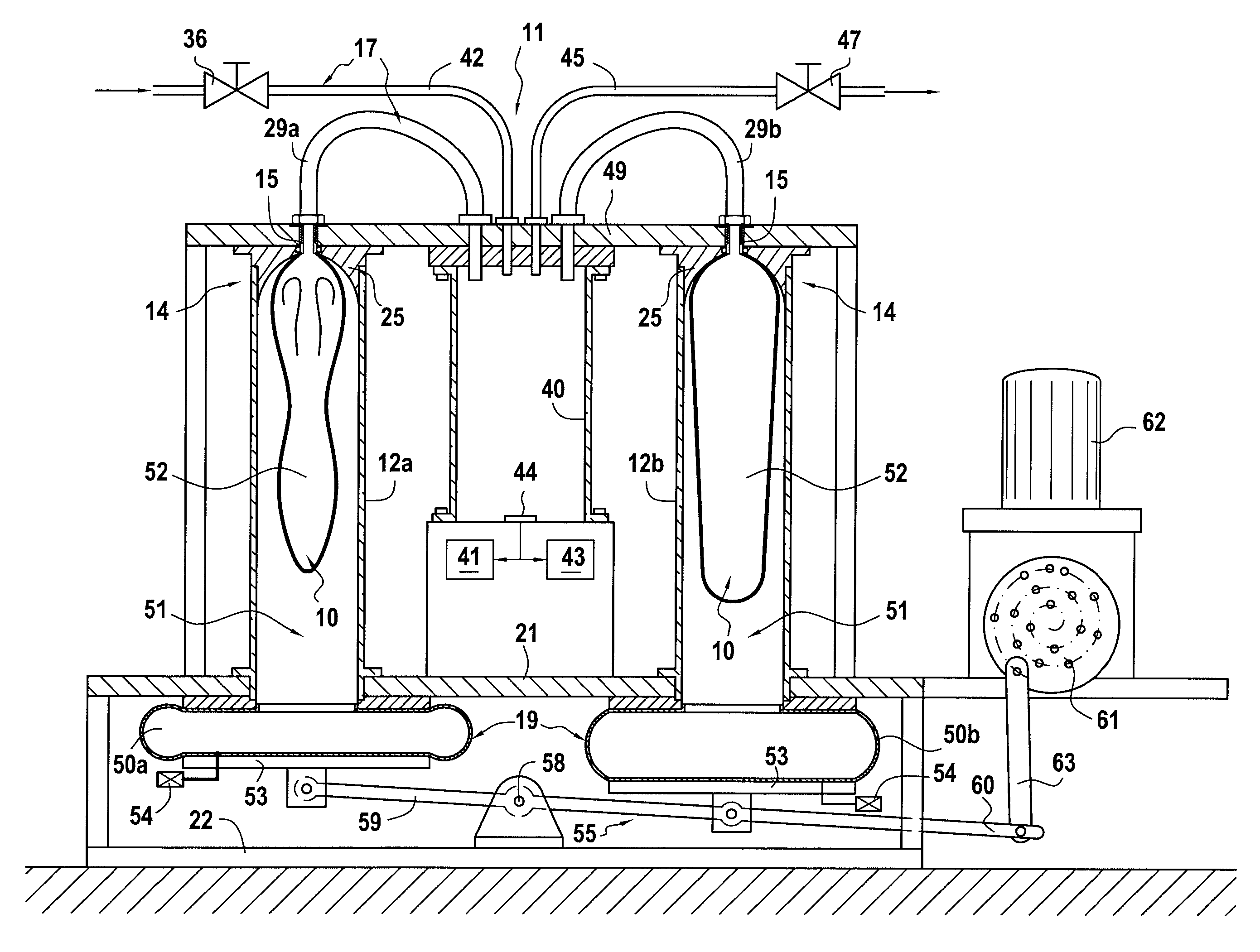
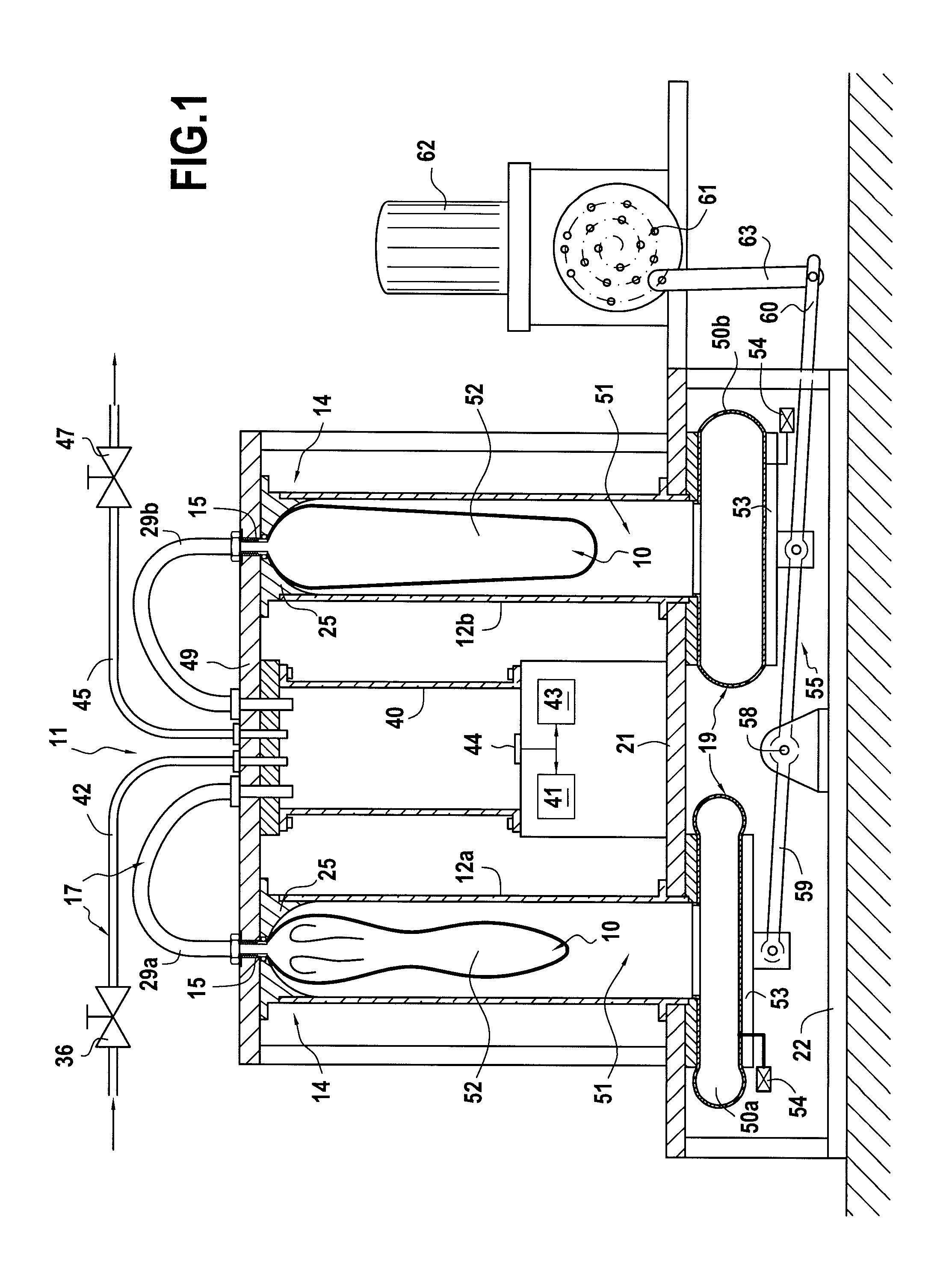
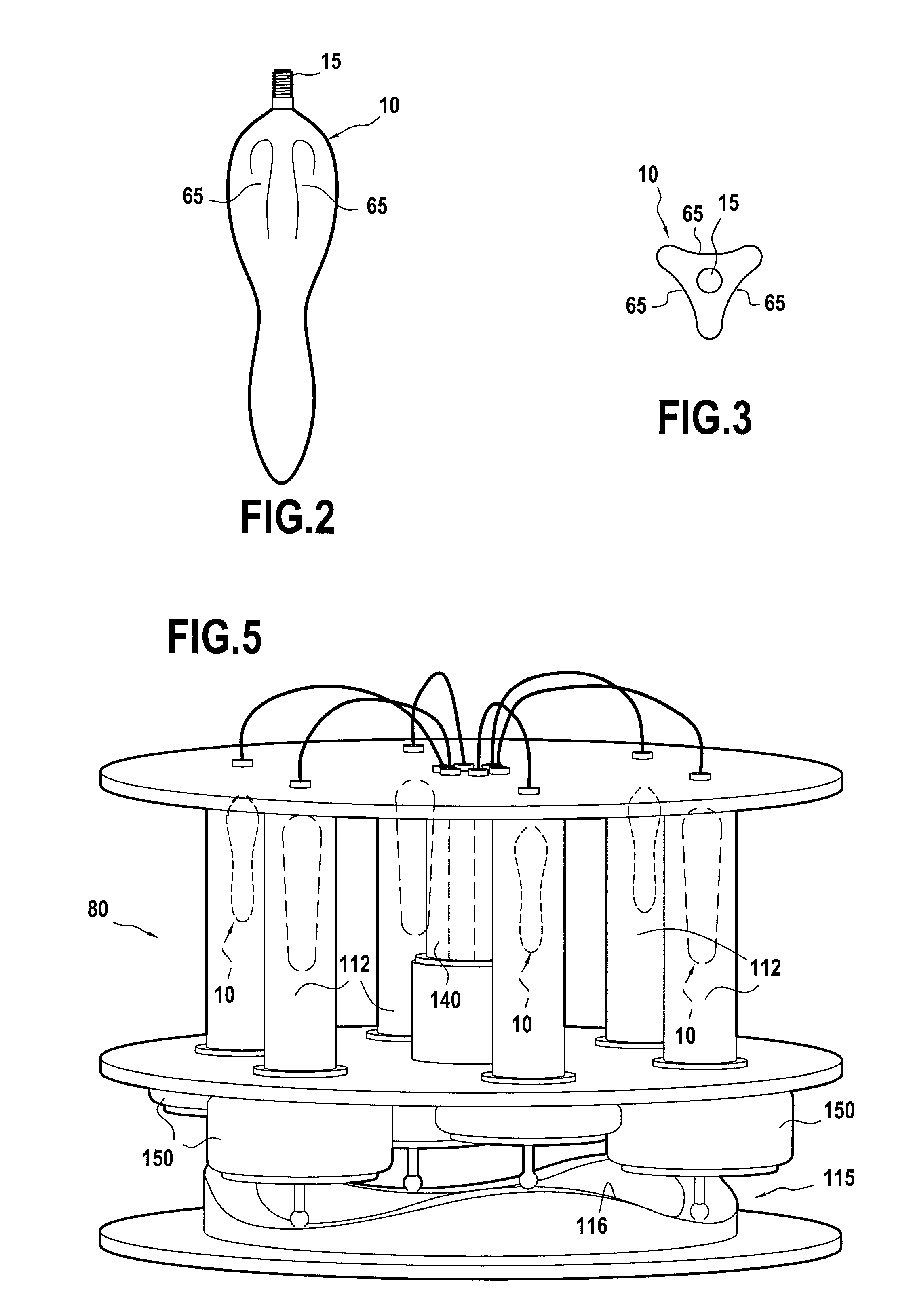
[0027]The device 11 shown in FIGS. 1 to 3 receives two identical flexible separators 10 in the form of “bladders”. In this example, it comprises two rigid chambers 12a, 12b that are generally cylindrical and tubular, each suitable for receiving one separator 10. At its top end, each chamber 12a, 12b includes a sealed connection arrangement 14 enabling a tubular endpiece 15 of the separator 10 to be fitted in leaktight manner to said top end. The device 11 may also have means 17 for enclosing a gas at a predetermined pressure within the separators (i.e. inside the “bladders”) and means 19 for moving a liquid cyclically into and out of each rigid chamber 12a, 12b, i.e. on the outside of the separator engaged therein. This cyclical motion of the liquid has the consequence of causing the separators filled with gas under pressure to describe deformation cycles that makes it possible to evaluate their lifetime.

[0028]In the example, both rigid chambers 12a, 12b are fastened vertically on a...


PUM

PropertyMeasurementUnit
pressureaaaaaaaaaa
pressureaaaaaaaaaa
pressureaaaaaaaaaa

Abstract

Testing the reliability of flexible separators arranged under conditions enabling the cycling rate of testing to be accelerated. According to the invention, two separators are enclosed in two rigid chambers, each defining a liquid capacity and a gas capacity. The two gas capacities communicate with each other, and each of the liquid capacities communicates with means for causing the volume of each of them to vary in alternation.

Description

FIELD OF THE INVENTION[0001]The invention relates to a method and a device for testing the reliability of a flexible separator associated with a rigid chamber and subdividing the chamber into a liquid capacity and a gas capacity of volumes that are variable, such as in particular the flexible separators that separate a liquid and a gas in so-called “hydraulic” accumulators.[0002]The variations in the respective volumes of the liquid and gas capacities give rise to repetitive deformation of the flexible separator and thus, after a certain length of time, to rupture of the flexible separator. The reliability of a flexible separator thus determines the reliability of the apparatus in which it is associated.BACKGROUND OF THE INVENTION[0003]In order to evaluate the reliability, e.g. of a hydraulic accumulator, it is known to mount such an accumulator fitted with a flexible separator on a test bench that includes means for causing the volume of liquid to vary cyclically, thereby deforming...

Claims


Application Information

Patent Timeline
Patent Type & Authority Patents(United States)
IPC IPC(8): G01N19/00G01M3/02G01M13/00G01N3/36
CPCG01N2203/0282G01M5/0075G01N2203/0067G01N2203/0016G01N3/36G01N2203/0042G01N2203/0007G01N2203/0048G01M5/0041
Inventor HOUSSAIS, ALAIN
Owner OLAER INDS
Why Eureka
Try Eureka