Wheel driving apparatus

a technology of driving apparatus and wheels, which is applied in the direction of motor deposition, propulsion parts, vehicle components, etc., can solve the problems of poor workability and great care required for tire exchange, and achieve the effect of improving the workability of wheel and tire exchang

Active Publication Date: 2013-12-31
TOYOTA JIDOSHA KK
View PDF21 Cites 8 Cited by
  • Summary
  • Abstract
  • Description
  • Claims
  • Application Information

AI Technical Summary

Benefits of technology

[0006]Accordingly, it is a general object of the present invention to provide a novel and useful wheel driving apparatus with an improved workability of exchanging wheels and tires
[0008]With the above aspect of the invention, the wheel is divided into at least two portions, i.e. the main body portion and the outside portion. Since the wheel can be divided, it is possible to detach only the outside portion of the wheel. It is also possible to attach the outside portion to the main body portion while keeping the rotor fixed to the main body portion of the wheel. According to the aspect of the present invention, it is possible to exchange the outside portion which is more vulnerable to damage than the main body portion of the wheel without removing the rotor from the main body portion of the wheel. Further, by detaching only the outside portion, it is possible to exchange a tire without removing a driving wheel from a vehicle body. According to the aspect of the present invention, a workability of exchanging the wheel driving apparatus can be improved.
[0014]With the above aspect of the invention, components of the motor are accommodated inside a spacial region formed between the side rib of the center portion and the side rib of the inside portion. Further, the side ribs extend along the entire inner periphery of the main body portion toward the rotational axis of the wheel, and the motor is retained between these ribs. Therefore, an efficiency of assembling motor components and wheel components is improved, and an annular rigidity or circle hardness of the main body portion of the wheel can be improved.
[0018]With the above aspect of the invention, the openings rotate when the wheel rotates and communicate with a cooling fluid chamber included in a spacial region. The cooling fluid enters the openings. The cooling fluid is carried upward by the openings along with rotation of the wheel, and concentrates on outer peripheral sides inside the openings around the rotational axis by a centrifugal force caused by the rotation. The outer peripheral sides inside the openings are positioned inside the outermost periphery of the circular coil end of the stator, the cooling fluid concentrated on the outer peripheral sides inside the openings moves toward the circular coil end of the stator. Thus, the cooling fluid tends to be discharged to an entire periphery of the circular coil end, thereby improving a cooling efficiency.
[0020]With the above aspect of the invention, the cooling fluid moves from the openings into the circular coil ends on inner and outer sides along the rotational axis. Thus the circular coil ends on the both sides of the stator can be easily cooled to improve a cooling efficiency.
[0022]With the above aspect of the invention, the bearings and the seals are arranged in the vicinity of the respective innermost diameters of the side ribs of the wheel. Therefore, it is possible to reduce relative circumferential speeds of the bearings and the seals, thereby extending mechanical lives of the bearings and the seals and improving reliabilities thereof.

Problems solved by technology

According to the wheel driving apparatus disclosed in Patent Document 1, great care is required for a tire exchange and workability of the tire exchange is poor.

Method used


Image

  • Wheel driving apparatus
  • Wheel driving apparatus
  • Wheel driving apparatus

Examples


Embodiment Construction

[0039]A description will now be given, with reference to FIG. 1A through FIG. 8B, of embodiments of the present invention.

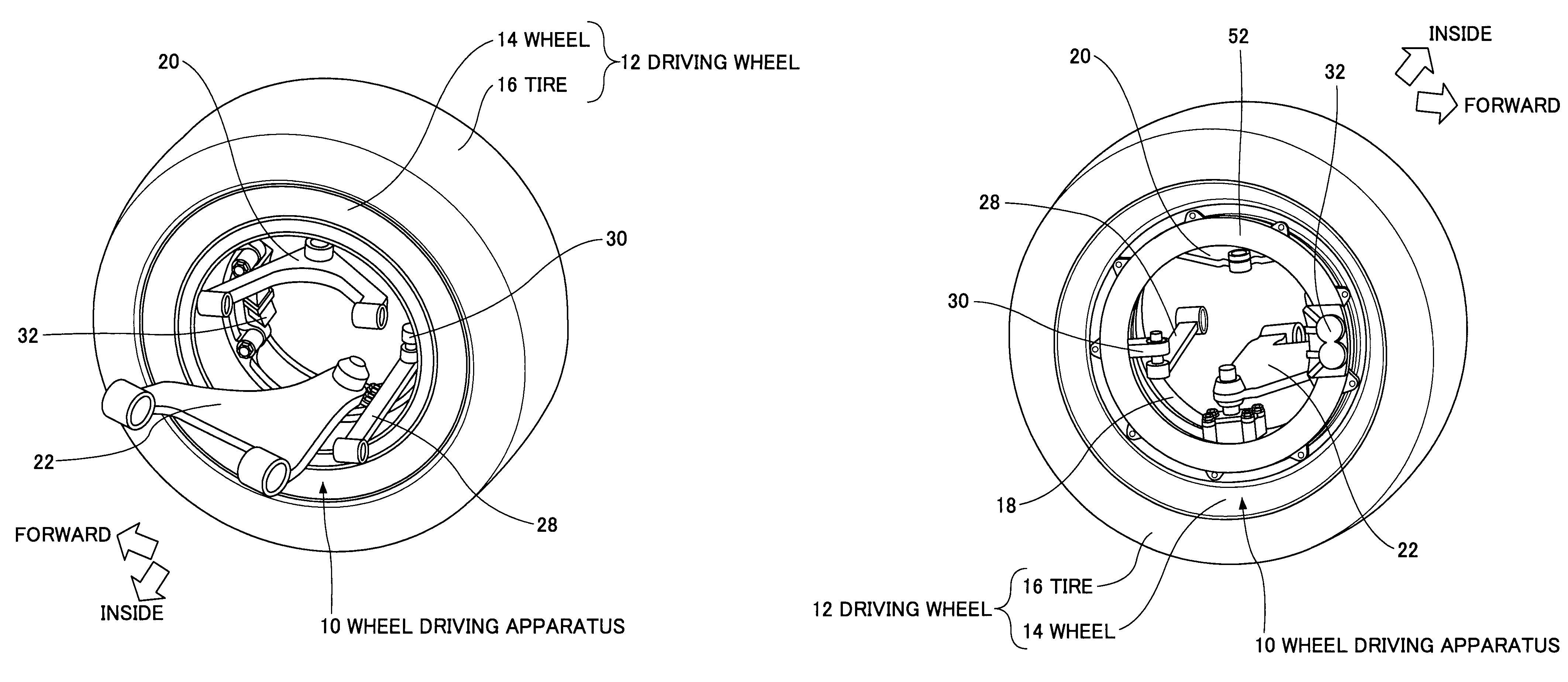
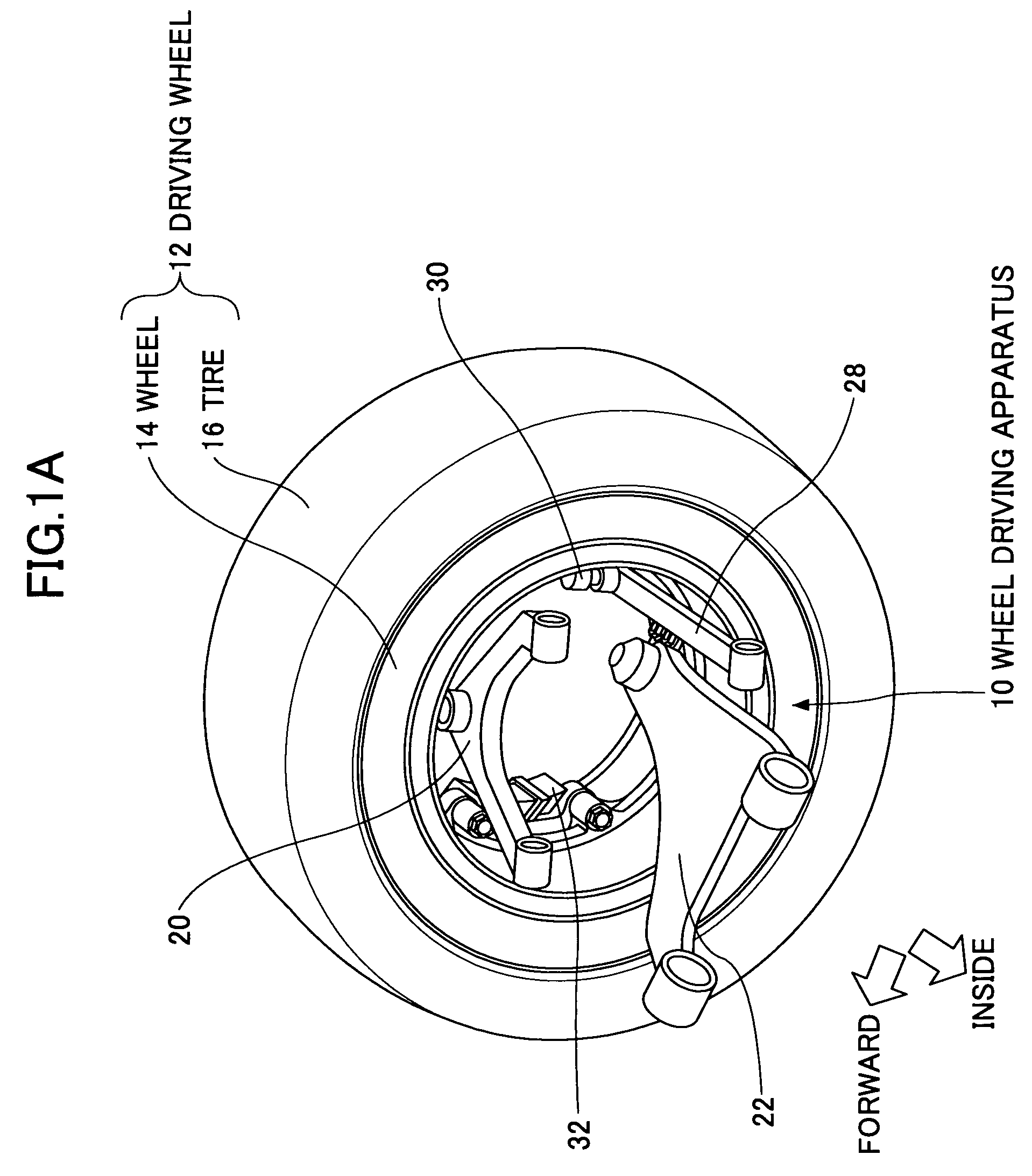
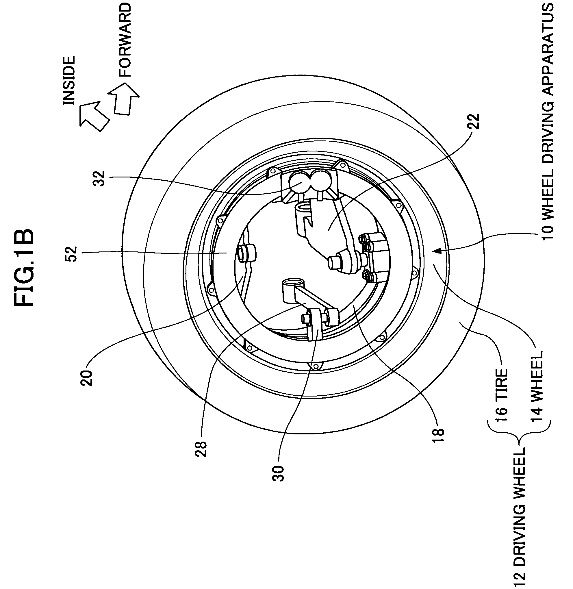
[0040]FIGS. 1A and 1B are perspective views for showing a driving wheel 12 equipped with a wheel driving apparatus 10 according to an embodiment of the present invention. FIG. 1A is viewed from an inner side of a vehicle and FIG. 1B is viewed from an outer side of the vehicle. FIG. 2 is a perspective view showing a main section of a wheel driving apparatus 10 of the embodiment by partially cutting away in a radial direction thereof.

[0041]The wheel driving apparatus 10 of this embodiment is respectively equipped in driving wheels of a vehicle to drive the driving wheels. The wheel driving apparatus is applied to an electric vehicle which is equipped with a motor as a driving power source inside its wheel. Because the structure of the embodiment is the same among the driving wheels, the explanation will be given to only one of the driving wheels. The structure may ...


PUM


Abstract

A wheel driving apparatus is provided. The wheel driving apparatus includes a cylindrical inner housing supported by a vehicle body via a suspension, a wheel supported by the cylindrical inner housing so that the wheel is rotatable relative to the cylindrical inner housing, a motor having a stator attached to the cylindrical inner housing and a rotor attached to the wheel. The wheel includes a main body portion and an outside portion positioned on an outer side of the vehicle body, and the rotor is attached to the main body portion.

Description

TECHNICAL FIELD[0001]The present invention generally relates to a wheel driving apparatus, and more particularly, to a wheel driving apparatus of a direct drive and outer rotor type which is configured by integrating a wheel and a motor.BACKGROUND ART[0002]Conventionally, a wheel is rotated to drive a vehicle using an in-wheel motor (vide, for example, Patent Document 1). This wheel driving apparatus employs a direct drive and outer rotor system. The in-wheel motor has a stator attached to a knuckle member serving as a housing on an inner peripheral side and a rotor attached to a wheel on an outer peripheral side, whereby the stator and the rotor are arranged opposite one another. In this wheel driving apparatus, the rotor is integrated with the wheel and rotation of the in-wheel motor is directly transmitted to the wheel.[0003]Patent Document 1: Japanese Unexamined Patent Application Publication No. 2004-115014[0004]In the wheel driving apparatus disclosed in Patent Document 1, the...

Claims


Application Information

Patent Timeline
Patent Type & Authority Patents(United States)
IPC IPC(8): B60K1/00
CPCB60K2007/0092B60B25/08B60B25/045B60K7/0007B60B25/20B60K2007/0038B60B25/12
Inventor MURATA, SATOSHI
Owner TOYOTA JIDOSHA KK
Why Eureka
Try Eureka