
Hybrid power systems

a hybrid power system and battery technology, applied in the direction of propulsion parts, gas pressure propulsion mounting, transportation and packaging, etc., can solve the problems of inefficiency of hybrid systems, high cost and heavy batteries used to power hybrid vehicles

Active Publication Date: 2013-12-31
ECHOGEN POWER SYST
View PDF436 Cites 66 Cited by
  • Summary
  • Abstract
  • Description
  • Claims
  • Application Information

AI Technical Summary

Benefits of technology

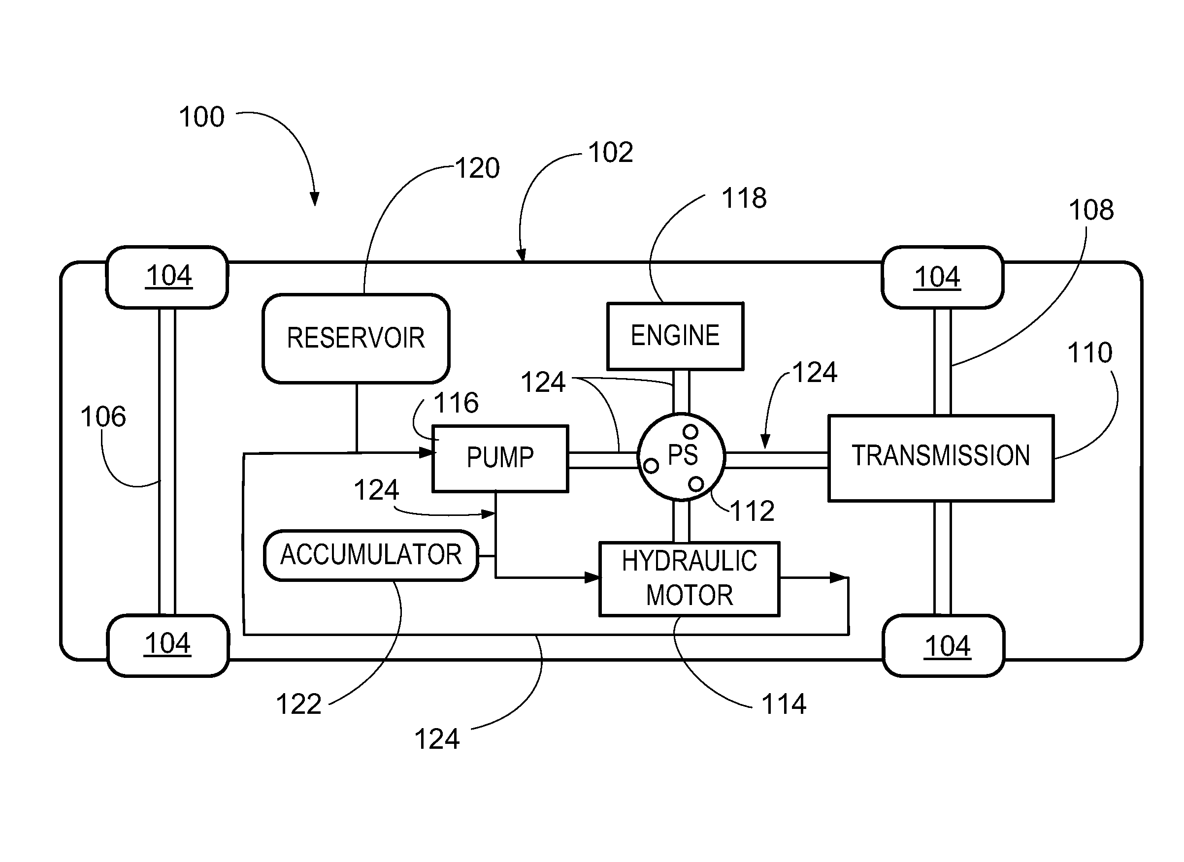
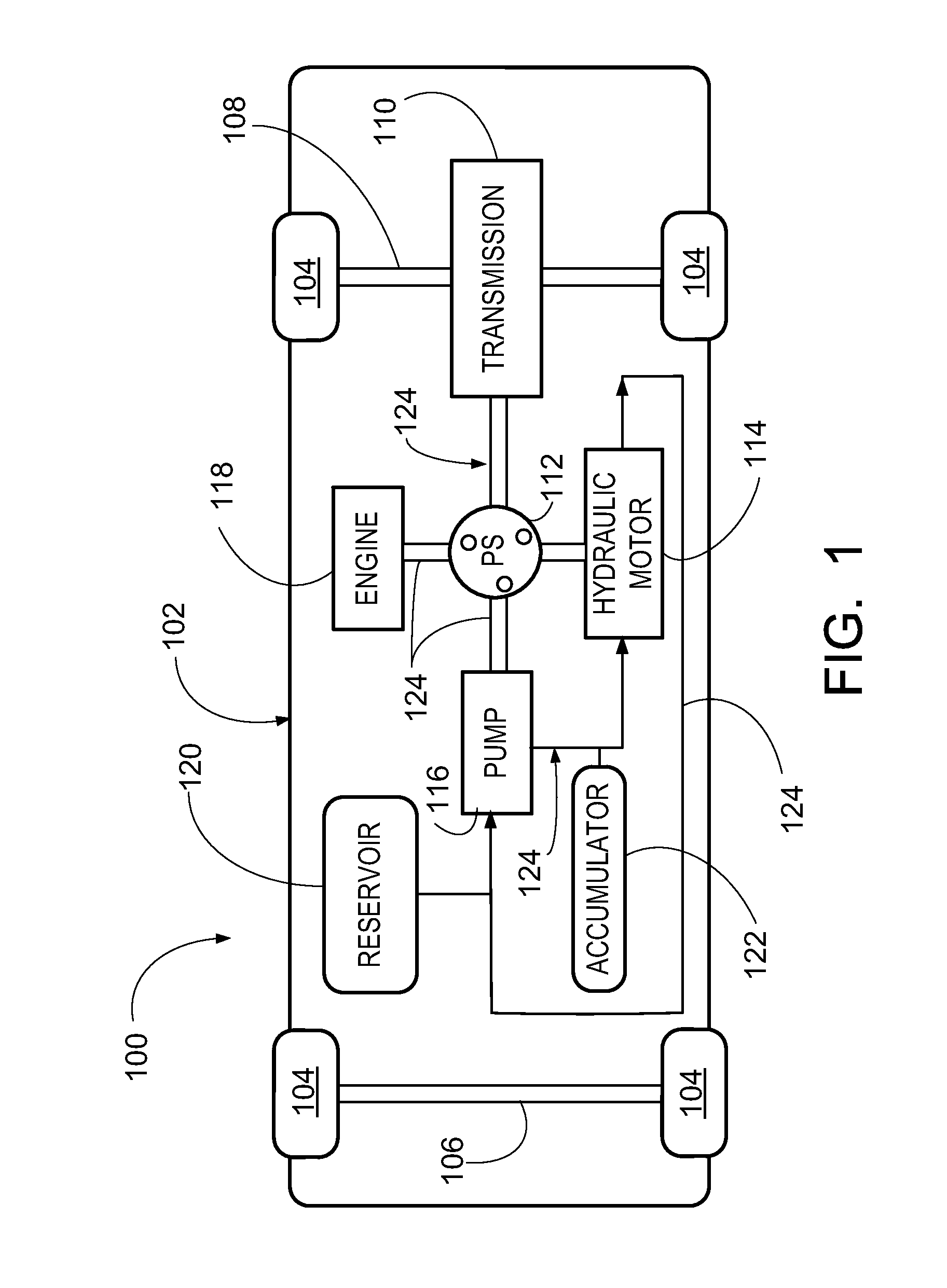
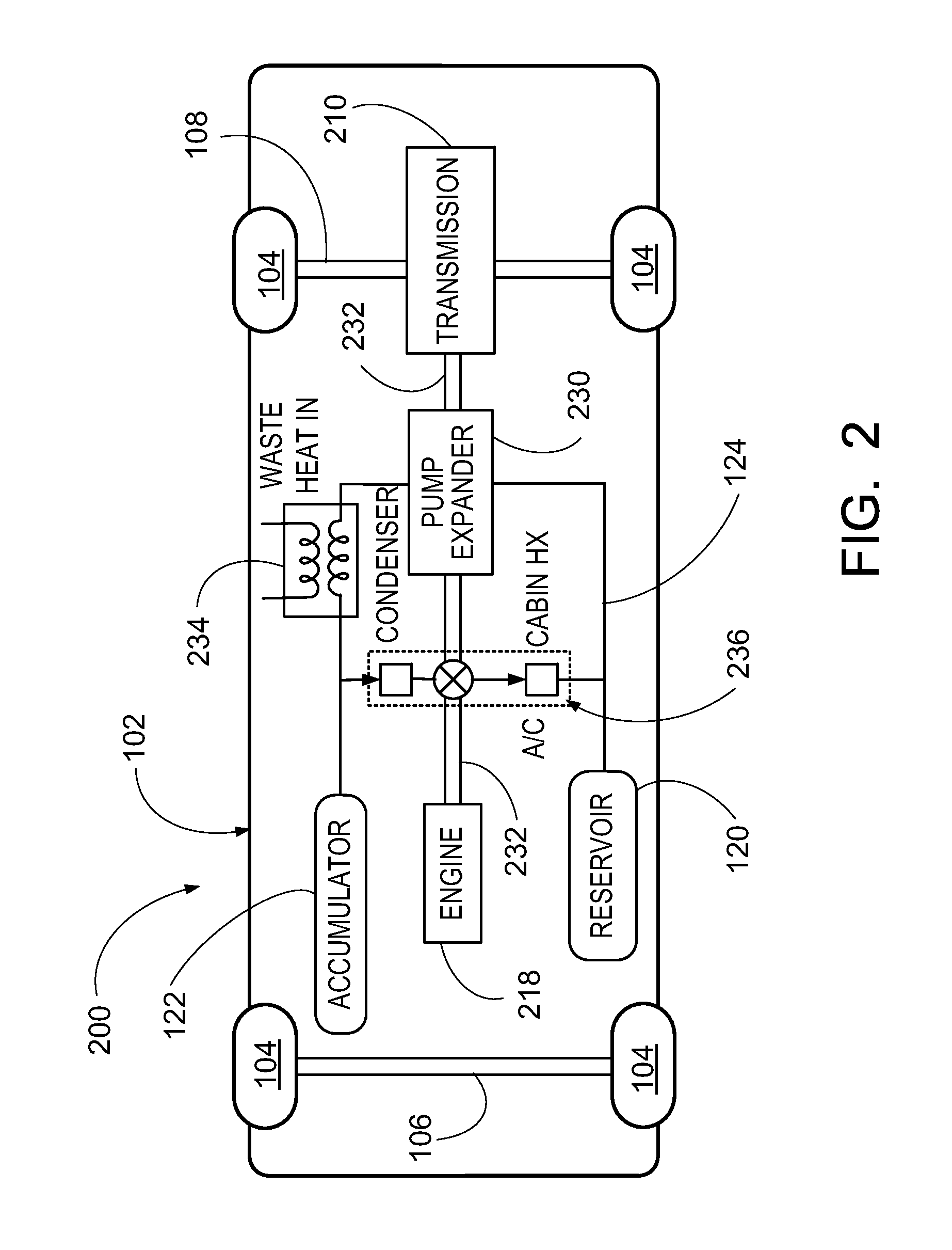
The present invention is about hybrid power systems for vehicles that use hydraulic systems to provide supplemental or even the primary motion power. These systems can provide both motion power and cabin comfort heating or cooling. The invention includes a power generating system and a passenger cabin comfort system, which consists of a thermodynamic working fluid, a pump, a motor, a high pressure accumulator, a low pressure reservoir, and at least one heat exchanger. The thermodynamic working fluid is concurrently operable to create either vehicle motion or electricity, and can also be used as a passenger shock absorber system. The invention also includes a hybrid vehicle comprising the power generating system and passenger cabin comfort system. The technical effects of the invention include improved efficiency, reduced emissions, and improved passenger comfort.

Problems solved by technology

As is well known in the art, the batteries that are used to power hybrid vehicles are both costly and heavy due to the number needed to yield a noticeable increase in vehicle fuel economy.
To date, all such hybrid, or alternative fuel, power systems have various drawbacks including, but not limited to, high cost, availability of fueling stations (e.g., hydrogen fueling stations for fuel cell vehicles only currently exist in a few select areas), technical disadvantages (e.g., hybrid systems can be inefficient because of the power drain produced by having to heat and / or cool a passenger compartment), etc.

Method used


Image

  • Hybrid power systems
  • Hybrid power systems
  • Hybrid power systems

Examples


Embodiment Construction

[0019]The present invention generally relates to hybrid power systems for vehicles. In one embodiment, the present invention relates to hybrid power systems for various types of transportation vehicles where the hybrid power systems is partially, or even totally, based on the use of at least one hydraulic system to provide supplemental, or even the primary, motion power for a hybrid vehicle. In another embodiment, the hybrid power systems of the present invention are capable of providing both motion power as well as cabin comfort heating and / or cooling. In still another embodiment, a hybrid vehicle according to the present invention comprises a power generating system and passenger cabin comfort system, wherein the power generating system comprises a thermodynamic working fluid (FA) in a first thermodynamic cycle (C1), a pump (P1), a motor (M1), a high pressure accumulator, a low pressure reservoir, and at least one heat exchanger, wherein the thermodynamic working fluid (FA) is con...


PUM


Abstract

The present invention generally relates to hybrid power systems for vehicles. In one embodiment, the present invention relates to hybrid power systems for various types of transportation vehicles where the hybrid power systems is partially, or even totally, based on the use of at least one hydraulic system to provide supplemental, or even the primary, motion power for a hybrid vehicle. In another embodiment, the hybrid power systems of the present invention are capable of providing both motion power as well as cabin comfort heating and / or cooling. In still another embodiment, a hybrid vehicle according to the present invention comprises a power generating system and passenger cabin comfort system, wherein the power generating system comprises a thermodynamic working fluid (FA) in a first thermodynamic cycle (C1), a pump (P1), a motor (M1), a high pressure accumulator, a low pressure reservoir, and at least one heat exchanger, wherein the thermodynamic working fluid (FA) is concurrently operable to create either vehicle motion through the motor (M1) or electricity through a generator and is operable to create passenger cabin cooling or heating through the expansion or contraction of the thermodynamic working fluid (FA).

Description

CROSS-REFERENCE TO RELATED APPLICATIONS[0001]This application claims benefit of U.S. Provisional Patent Application No. 61 / 209,760, entitled “Hybrid Power Systems,” filed Mar. 11, 2009, is hereby incorporated by reference herein in its entirety.FIELD OF THE INVENTION[0002]The present invention generally relates to hybrid power systems for vehicles. In one embodiment, the present invention relates to hybrid power systems for various types of transportation vehicles where the hybrid power systems is partially, or even totally, based on the use of at least one hydraulic system to provide supplemental, or even the primary, motion power for a hybrid vehicle. In another embodiment, the hybrid power systems of the present invention are capable of providing both motion power as well as cabin comfort heating and / or cooling. In still another embodiment, a hybrid vehicle according to the present invention comprises a power generating system and passenger cabin comfort system, wherein the power...

Claims


Application Information

Patent Timeline
IPC IPC(8): B60K6/00B60K25/10
CPCB60H1/004B60K25/10Y02T10/6208B60K6/00B60K6/12B60H1/0045Y02T10/62
Inventor GURIN, MICHAEL, H.
Owner ECHOGEN POWER SYST
Learn More