Ladder securing apparatus

a technology for securing equipment and ladders, which is applied in the direction of scaffolding, machine supports, scaffold accessories, etc., can solve the problems of not being able to easily access the means, not being able to tie or secure ladders to the adjacent surface, and significant safety risks for workers, so as to avoid the risk of falling

Inactive Publication Date: 2013-12-31
MOSIER TIM
View PDF12 Cites 8 Cited by
  • Summary
  • Abstract
  • Description
  • Claims
  • Application Information

AI Technical Summary

Benefits of technology

[0009]The present invention is directed to an apparatus to secure a ladder in place to a ferromagnetic surface, such surfaces including but not limited to metal storage tanks. The invention does not require the worker to climb the ladder before securing the ladder in place, thus avoiding the risk of fall during the process of climbing and securing the ladder.

Problems solved by technology

In certain applications, however, it is not practical to tie or secure the ladder to the adjacent surface.
The sides of these tanks are typically smooth, and contain no readily available means by which the top of a ladder may be secured.
As a result, workers have no alternative but to use these ladders without securing them in place, which creates a significant safety risk for the worker.
The risk to the worker is particularly great since painting and related work on a tank may require the worker to lean sideward from the ladder, increasing the risk that the ladder may slip during use.
The movements necessary for the worker to secure the ladder in place may themselves lead to a slippage of the ladder, thus creating a risk associated with the very act intended to increase the safety of the further use of the ladder.

Method used


Image

  • Ladder securing apparatus
  • Ladder securing apparatus
  • Ladder securing apparatus

Examples


Embodiment Construction

)

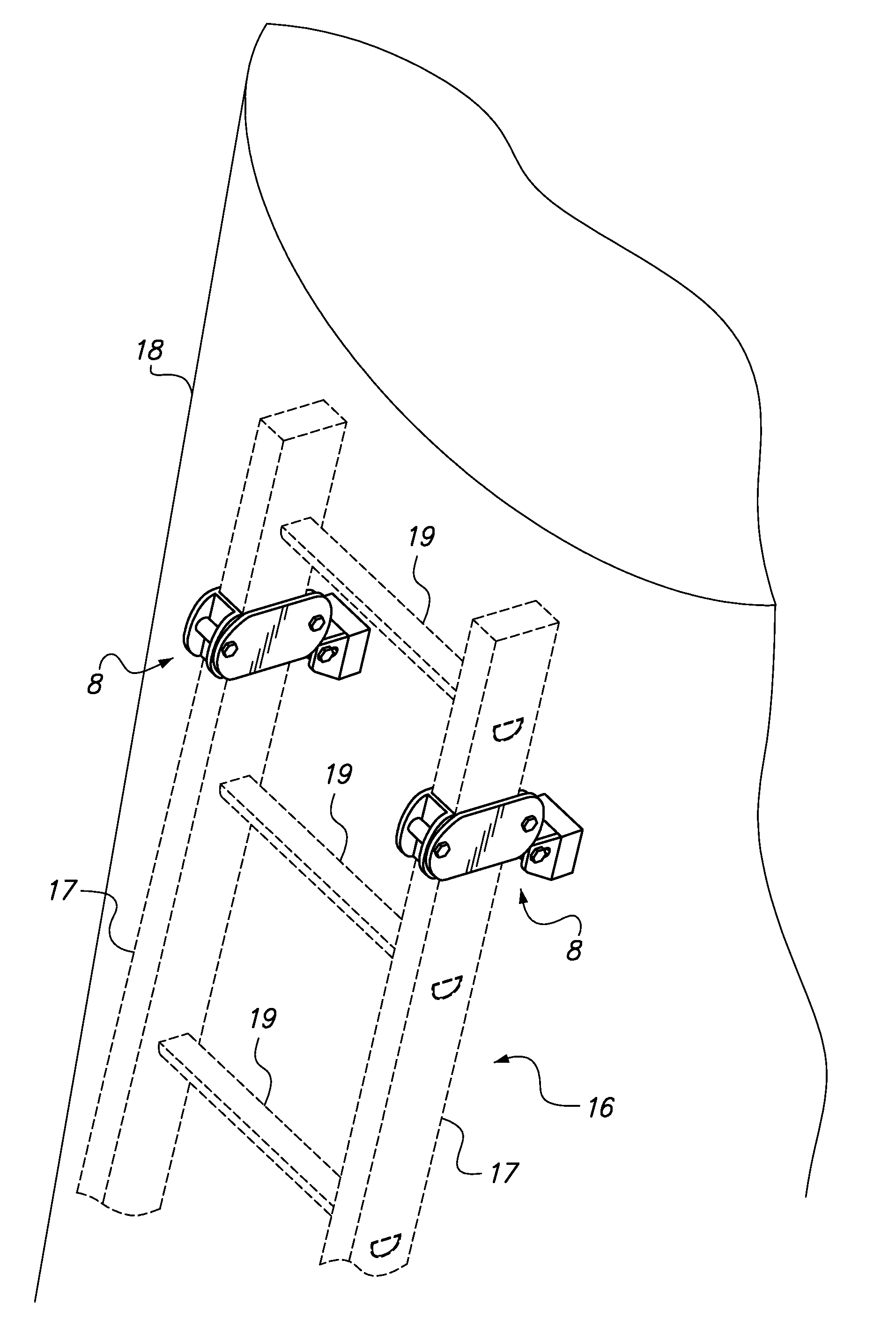
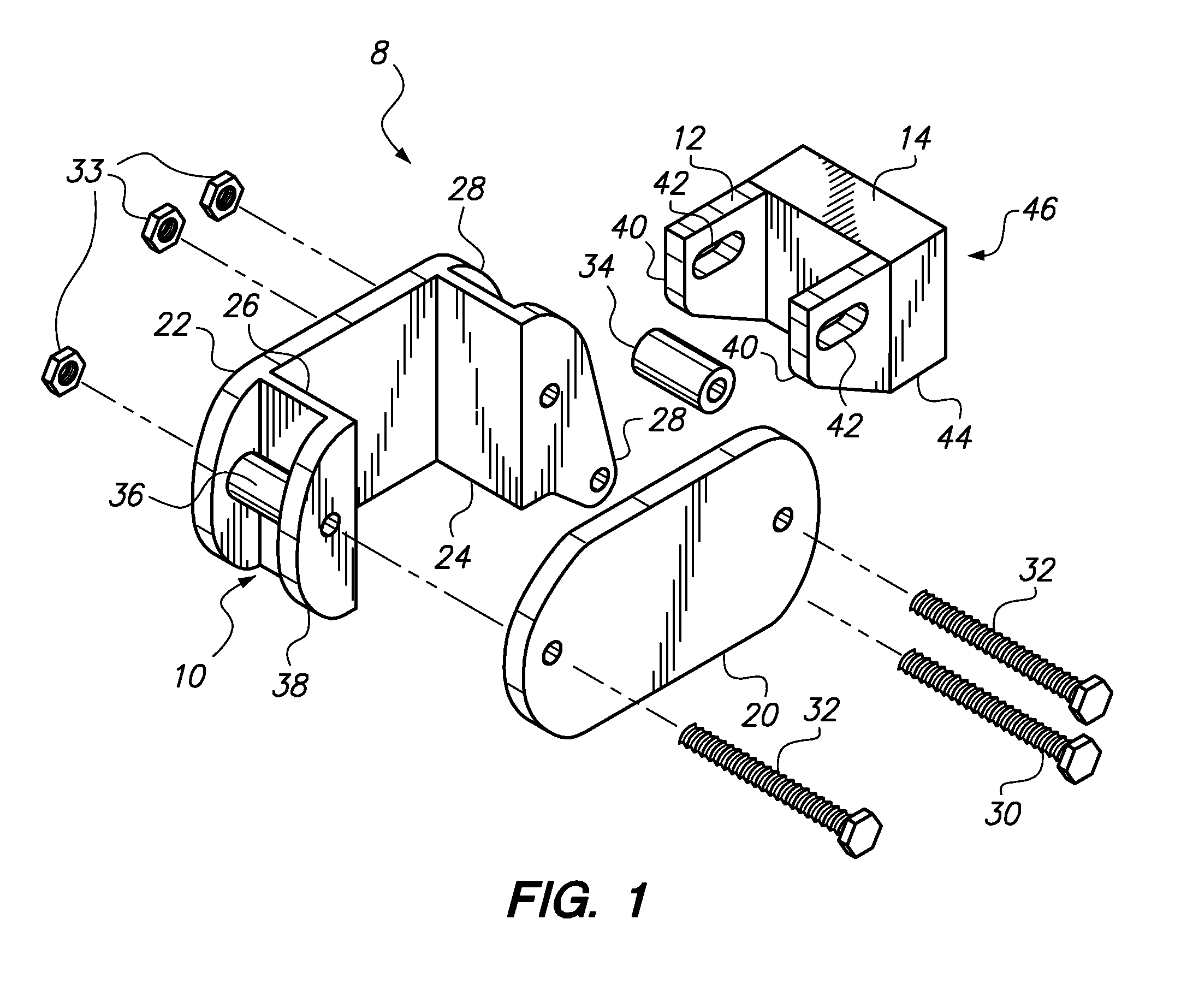
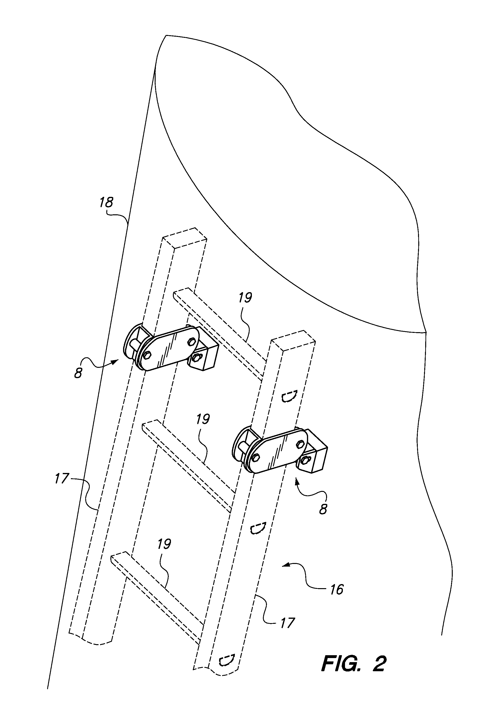
[0016]With reference to FIG. 1, an attachment 8 according to a preferred embodiment of the present invention may be described. As illustrated in FIG. 2, two such attachments 8 are used to secure a ladder 16 to a storage tank 18 or other ferromagnetic surface.

[0017]Each attachment 8 is formed of a bracket 10, a magnet mount 12, and a magnet 14. Bracket 10 includes two plates that form its longer sides, first bracket plate 20 and second bracket plate 22. These plates are fitted, as shown in FIG. 2, to stringers 17 of ladder 16 such that they are perpendicular to rungs 19 of ladder 16.

[0018]Second bracket plate 22 has first sidewall 24 and second sidewall 26 extending therefrom, with first bracket plate 20 pressed against the extending ends of first sidewall 24 and second sidewall 26, resulting in a partially enclosed space sized to receive a stringer 17 or ladder 16. Flange wing 28 extends from first sidewall 24, parallel to second bracket plate 22. Likewise, support wing 38 extends ...


PUM


Abstract

An apparatus to secure a ladder to a ferromagnetic work surface, such as a metal storage tank, comprises a pair of brackets removably attached near the top of the ladder. The brackets are hinged to magnet mounts, which each hold a permanent magnet that releasably holds the ladder in place against the work surface. The apparatus prevents the ladder from slipping while a worker is climbing the ladder or while working from the ladder.

Description

CROSS-REFERENCE TO RELATED APPLICATIONS[0001]Not applicable.STATEMENT REGARDING FEDERALLY SPONSORED RESEARCH OR DEVELOPMENT[0002]Not applicable.BACKGROUND OF THE INVENTION[0003]The invention is directed to an apparatus for securing a ladder in a desired position, and in particular to such an apparatus that is used to secure a ladder to a ferromagnetic surface.[0004]Portable ladders, and in particular the leaning-type extension ladders usually constructed of aluminum or fiberglass, are well known in the art. Such ladders are commonly employed for many industrial applications where a worker much reach a relatively high area in order to perform, for example, a maintenance or repair operation.[0005]In order to prevent slippage and resulting injury due to a fall, it is a common safety practice to tie or otherwise secure the top of a portable leaning-type ladder to the adjacent surface during its use. In certain applications, however, it is not practical to tie or secure the ladder to the...

Claims


Application Information

Patent Timeline
Patent Type & Authority Patents(United States)
IPC IPC(8): E06C7/00A47G1/17
CPCE06C7/188E06C7/48E06C7/00
Inventor MOSIER, TIM
Owner MOSIER TIM
Why Eureka
Try Eureka