
Suction gripper for food

a technology for sucking grippers and food, applied in the direction of manipulators, gripping heads, kitchen equipment, etc., can solve the problems of sucking grippers and prone to soiling, and achieve the effect of effective and gentle fruit unfolding

Active Publication Date: 2013-12-31
DEUTES INSTITUT FUR LEBENSMITTELTECHN
View PDF10 Cites 8 Cited by
  • Summary
  • Abstract
  • Description
  • Claims
  • Application Information

AI Technical Summary

Benefits of technology

The patent text describes a suction gripper device with a holding device for food items, such as fruits and vegetables, which can be easily filled or hollowed out for further processing. The device uses low pressure to gently unfold the food item and restore its original hollow shape, making it easier to fill. The technical effect of this invention is to provide a food holding and processing device that can efficiently hold, hold, and fill food items while maintaining their natural shape.

Problems solved by technology

Known suction grippers, in case they have a low-pressure source or a pump for generation of low pressure, are prone for soiling, since adherences or loose components of the sucked-up commodity reach the low-pressure pipelines through the suction opening.

Method used


Image

  • Suction gripper for food
  • Suction gripper for food
  • Suction gripper for food

Examples


Embodiment Construction

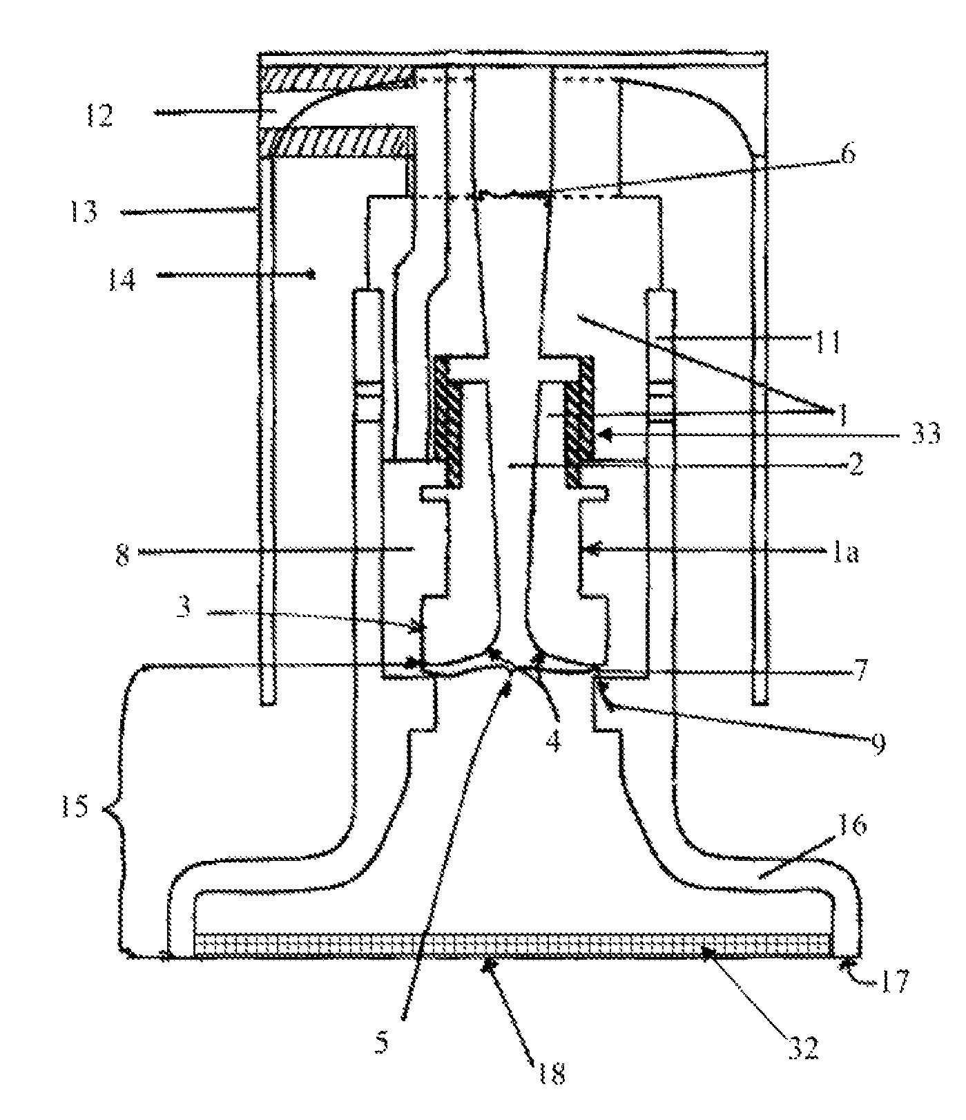
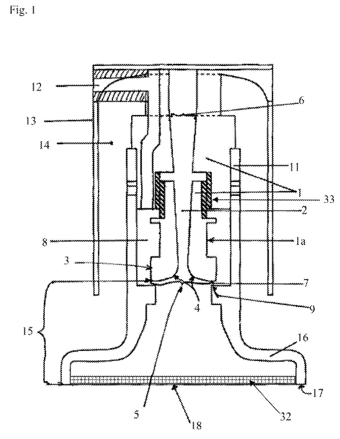
[0043]In the Figures, the reference numbers denote functionally equal elements. The details described in the Figures are combinable in accordance with the invention, also when described with reference to different Figures.

[0044]As depicted in FIG. 1, the suction gripper has a central well 1 in which a central channel 2 is arranged, preferably coaxially to the central well 1. At the first end 3 of the central channel 2 a convex surface 4 of the central channel 2 opens up the first opening 5 of the central channel 2. The convex surface 4 extends from the smallest cross-section of the central channel 2 into the plane in which the first opening 5 is opened up. Preferably, the convex surface 4 in perpendicular to the longitudinal axis of the central channel 2 has a parabolic cross-section the incline of which increases from the plane in which the first opening 5 is arranged towards the section of the central channel 2 having the smallest cross-section. Opposite the plane in which the fir...


PUM


Abstract

A suction gripper has a driver that is a compressed-air source. The suction gripper has a suction opening opened up by a pipe section forming a suction section. At a distance from the suction opening, a convex surface is arranged spaced from the suction section by an annular outlet. The suction gripper has a central channel formed in a central well. The central channel has a first opening opened up by a convex surface around the central channel. The central channel adjacent to the convex surface has its smallest cross-section and from this broadens towards the second opening opposite the first opening. In a particular suction gripper, the annular outlet is formed by a section of the convex surface spaced radially from the longitudinal axis of the central channel and by a shoulder spaced axially thereto, which covers the convex surface at least in an annular region.

Description

[0001]The invention relates to a suction gripper, also named vacuum gripper, for periodic and cyclic lifting of objects, respectively, against a suction opening and for putting down of the objects from the suction opening as well as to the use of the suction gripper as a lifting device, especially for food, as well as to a method for cyclic lifting and transporting of objects, respectively, especially of food by means of the suction gripper. The suction gripper according to the invention has a suction opening in which low pressure is produced with a drive which consists of a compressed-air source such that the suction gripper is built and works without a low-pressure source and without electrical drive for the generation of low pressure.STATE OF THE ART[0002]For the transport of objects it is generally known to arrange suction grippers at their surfaces which by means of a connected low-pressure source or by a built-in vacuum pump produce a low pressure.[0003]EP 2149517 A2 describes...

Claims


Application Information

Patent Timeline
Patent Type & Authority Patents(United States)
IPC IPC(8): B25J15/06
CPCB26D2210/02B26D7/018B26D2007/011B65G47/911B65G2201/0202
Inventor HUKELMANN, BERNHARDFRANKE, KNUTHEINZ, VOLKER
Owner DEUTES INSTITUT FUR LEBENSMITTELTECHN
Learn More