
Terminal fitting and a method for forming a fluid-proof terminated wire assembly

a technology of terminating wire and terminating wire, which is applied in the direction of connection insulation, connection formation by deformation, coupling device connection, etc., can solve the problems of insufficient adhesion of waterproof material to the core and insufficient formation of excess material, so as to reduce the operational burden

Inactive Publication Date: 2013-12-31
SUMITOMO WIRING SYST LTD
View PDF7 Cites 10 Cited by
  • Summary
  • Abstract
  • Description
  • Claims
  • Application Information

AI Technical Summary

Benefits of technology

This patent describes a technique for making a connector housing that has a recessed groove and an insulation barrel without needing to enlarge the housing. This means that the insulation barrel doesn't interfere with the inner surface of a cavity when the terminal fitting is inserted. The front end of the insulation coating is located in the range of the recessed groove, which helps to reliably adhere to the core without needing to adjust the margin. Overall, this technique simplifies the manufacturing process and reduces operational burden.

Problems solved by technology

Thus, the above-described recess is not formed and the waterproof material may not sufficiently adhere to a core 5.
However, in this case, the front end of the insulation coating 3 may be located inside the insulation barrel 1 since it is difficult to adjust the projecting margin A. In such a case, the waterproof material does not spread to the inside of the insulation barrel 1 and may not adhere to a part of the core 5 located inside the insulation barrel 1.

Method used


Image

  • Terminal fitting and a method for forming a fluid-proof terminated wire assembly
  • Terminal fitting and a method for forming a fluid-proof terminated wire assembly
  • Terminal fitting and a method for forming a fluid-proof terminated wire assembly

Examples


Embodiment Construction

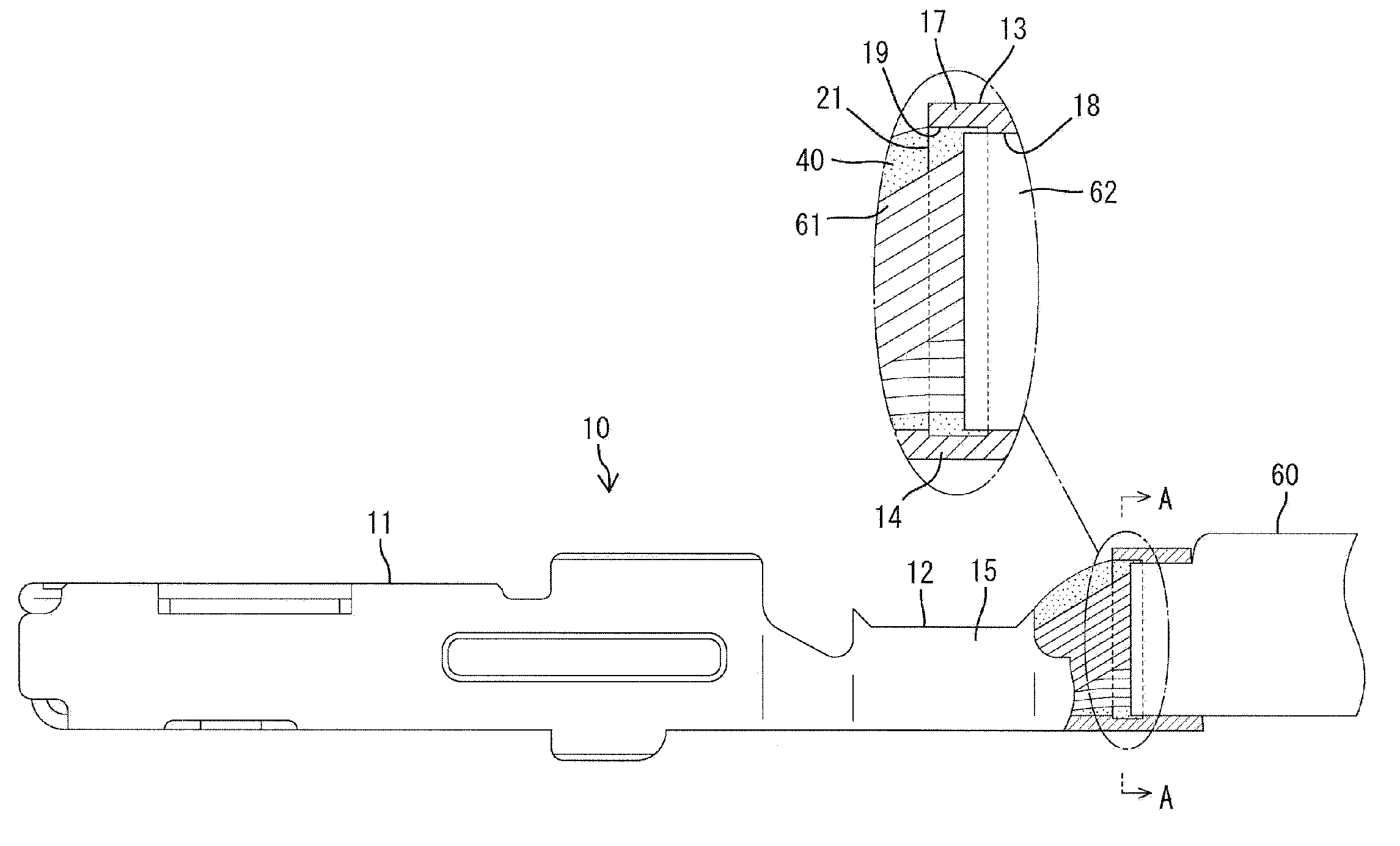
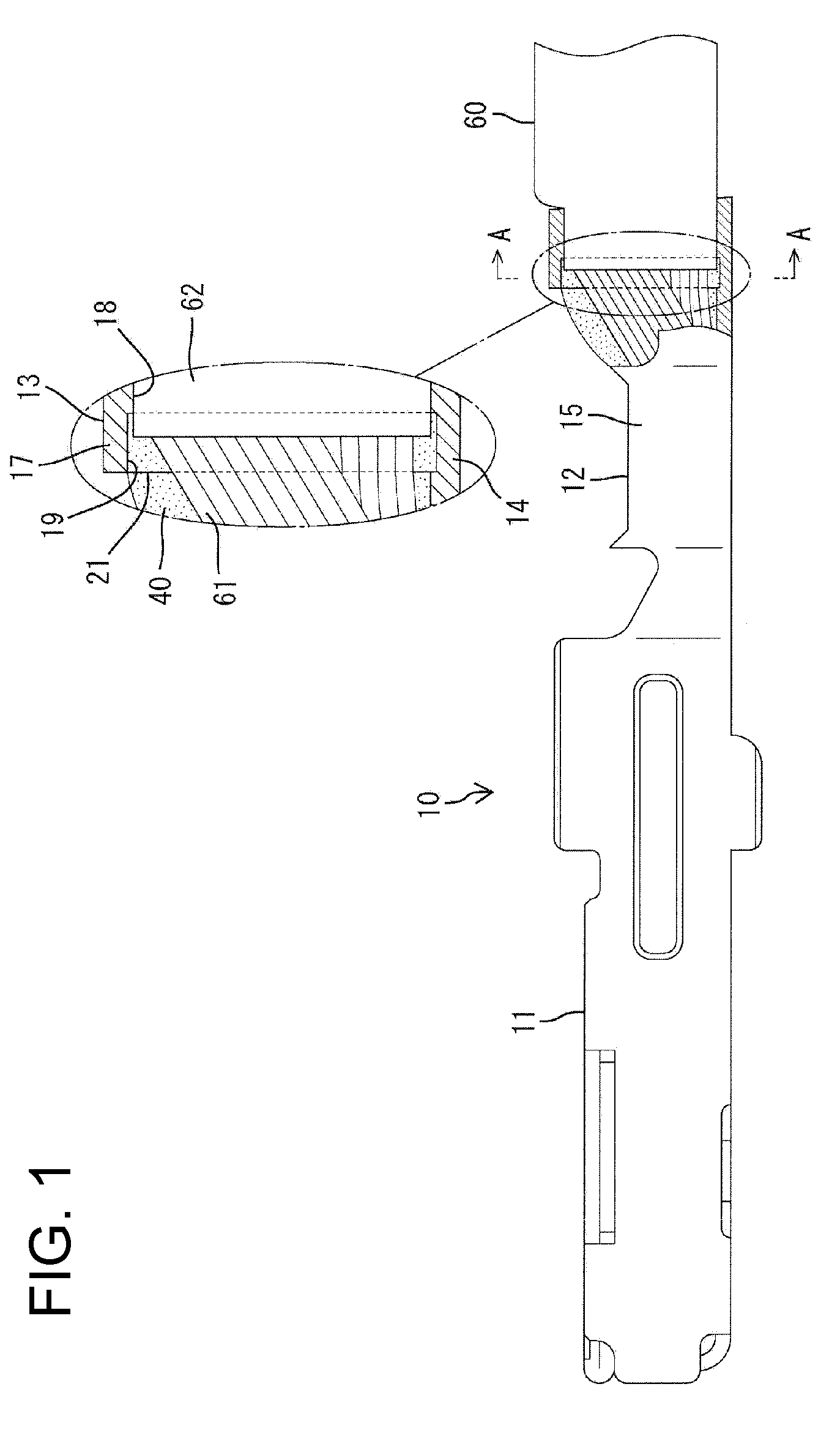
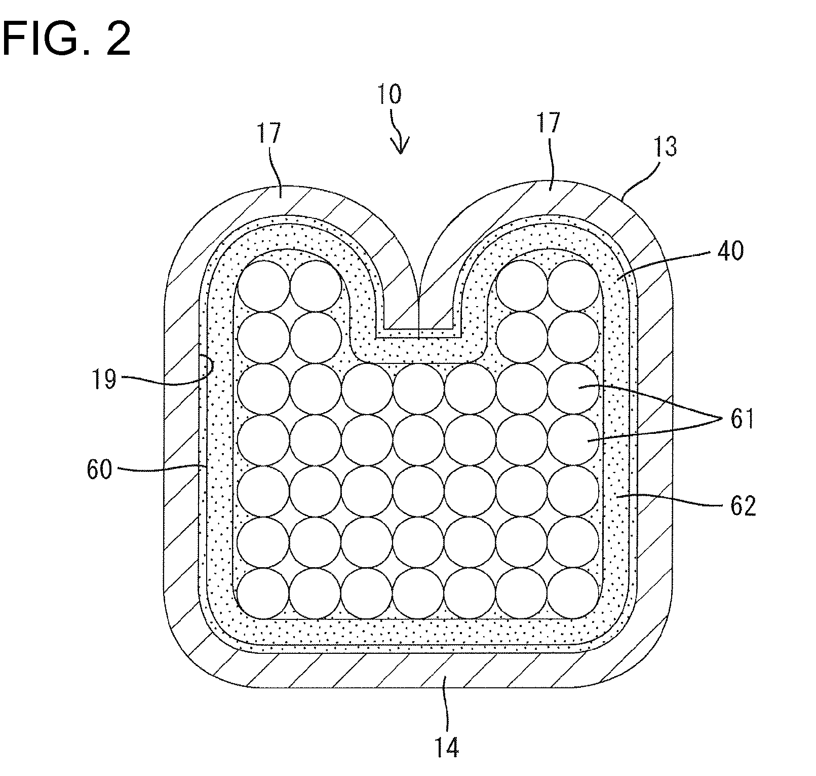
[0021]A terminal fitting in accordance with the invention is identified by the numeral 10 and is formed unitarily by bending, folding and / or embossing process and the like on an electrically conductive plate made e.g. of copper or copper alloy and to be connected to an end portion of a wire 60.

[0022]The wire 60 comprises an electrically conductive core 61, for example, made of aluminum or aluminum alloy and an insulation coating 62 made e.g. of resin covering the core 61. The core 61 is exposed e.g. by stripping off the insulation coating 62 at the end portion of the wire 60.

[0023]A main portion 11 is formed at a front part of the terminal fitting 10 and is in the form of a substantially rectangular tube. An unillustrated resiliently deformable contact piece particularly is formed in the main portion 11. A male tab of an unillustrated mating terminal fitting is inserted into the main portion 11 as connectors are connected and resiliently contacts the resilient contact piece so that ...


PUM

PropertyMeasurementUnit
electrically conductiveaaaaaaaaaa
circumferenceaaaaaaaaaa
thicknessaaaaaaaaaa

Abstract

A terminal fitting (10) includes a wire barrel (12) to be crimped and connected to a core (61) at an end portion of a wire (60). An insulation barrel (13) is located behind the wire barrel (12) and is to be crimped and connected to an insulation coating (62) at the end portion of the wire (60). The inner surface of the insulation barrel (13) is formed with a close-contact portion (18) to be held in close contact with the insulation coating (62) and a recessed groove (19) spaced from the insulation coating (62) and extending over the entire circumference. The recessed groove (19) has an opening (21) that is open at the front end of the insulation barrel (13) and a waterproof material (40) flows into the recessed groove (19) through the opening (21). The waterproof material (40) adheres to the outer surface of the core (61).

Description

BACKGROUND OF THE INVENTION[0001]1. Field of the Invention[0002]The invention relates to a terminal fitting and a method for forming a fluid-proof terminated wire assembly.[0003]2. Description of the Related Art[0004]Japanese Unexamined Patent Publication No. 2010-49941 discloses a terminal fitting formed by bending an electrically conductive metal plate and includes a wire barrel to be crimped and connected to a core at an end of a wire. An insulation barrel is located behind the wire barrel and is to be crimped and connected to an insulation coating at the end portion of the wire. The outer surface of the core is coated with a waterproof resin to ensure waterproofness of a connected part with the core. This waterproof material also is caused to flow into a recess defined by the rear end of the wire barrel, the front end of the insulation barrel and the outer surface of the core to adhere to the entire outer surface of the core.[0005]In the above conventional terminal fitting, if a...

Claims


Application Information

Patent Timeline
Patent Type & Authority Patents(United States)
IPC IPC(8): H01R4/10
CPCH01R13/5216H01R4/184H01R4/188H01R4/185H01R4/70Y10T29/49185
Inventor UCHIYAMA, YOSHIHIRO
Owner SUMITOMO WIRING SYST LTD
Learn More