Ultrasonic transducer and ultrasonic diagnostic device using same

a transducer and ultrasonic technology, applied in the field of ultrasonic transducers and ultrasonic diagnostic devices, can solve the problems of reducing the insulation withstand voltage of the insulating film, the inability to use a larger direct current voltage or alternate current voltage, so as to improve reception sensitivity or transmission sound pressure, reduce the insulation withstand voltage, and suppress accumulation

Active Publication Date: 2013-12-31
FUJIFILM HEALTHCARE CORP
View PDF13 Cites 17 Cited by
  • Summary
  • Abstract
  • Description
  • Claims
  • Application Information

AI Technical Summary

Benefits of technology

[0017]The present invention provides a structure of CMUT for suppressing accumulation of electrical charge in an insulating film between upper and lower electrodes and reduction of insulation withstand voltage thereof even when surfaces above and below the hollow part contact with each other, and an ultrasonic diagnostic device using it. The present invention also provides a CMUT that can improve reception sensitivity and transmission sound pressure compared with those of conventional CMUTs while securing reliability, and an ultrasonic diagnostic device using it.

Problems solved by technology

Further, since electrical charge is accumulated in the floating electrode beforehand, when the surfaces above and below the hollow part contact with each other, accumulation of electrical charge in the insulating film between the floating electrode and the upper electrode or lower electrode and reduction of the insulation withstand voltage of the insulating film are unavoidable.
As described above, because of the problems caused by the contact of the surfaces above and below the hollow part, it is difficult to use a larger direct current voltage or alternate current voltage, i.e., improve reception sensitivity or transmission sound pressure, in the conventional transducers according to the conventional techniques.

Method used


Image

  • Ultrasonic transducer and ultrasonic diagnostic device using same
  • Ultrasonic transducer and ultrasonic diagnostic device using same
  • Ultrasonic transducer and ultrasonic diagnostic device using same

Examples


embodiment 1

[0068]In the embodiment 1, the object of suppressing accumulation of electrical charge in an insulating film and reduction of insulation withstand voltage thereof even when surfaces above and below the hollow part contact with each other at the time of driving is achieved by disposing a conductive film so as to be exposed to the hollow part from the underside of the hollow part.

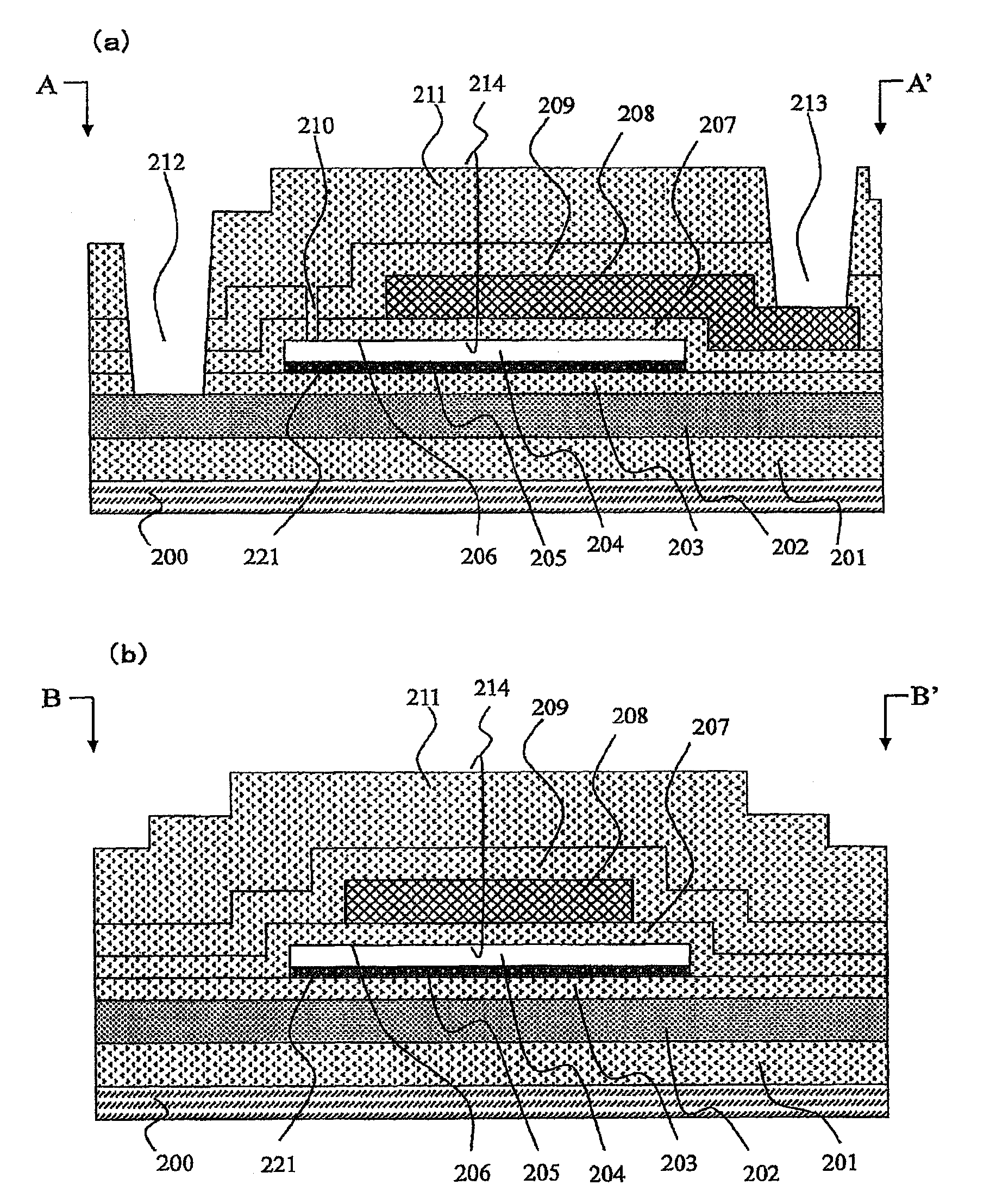
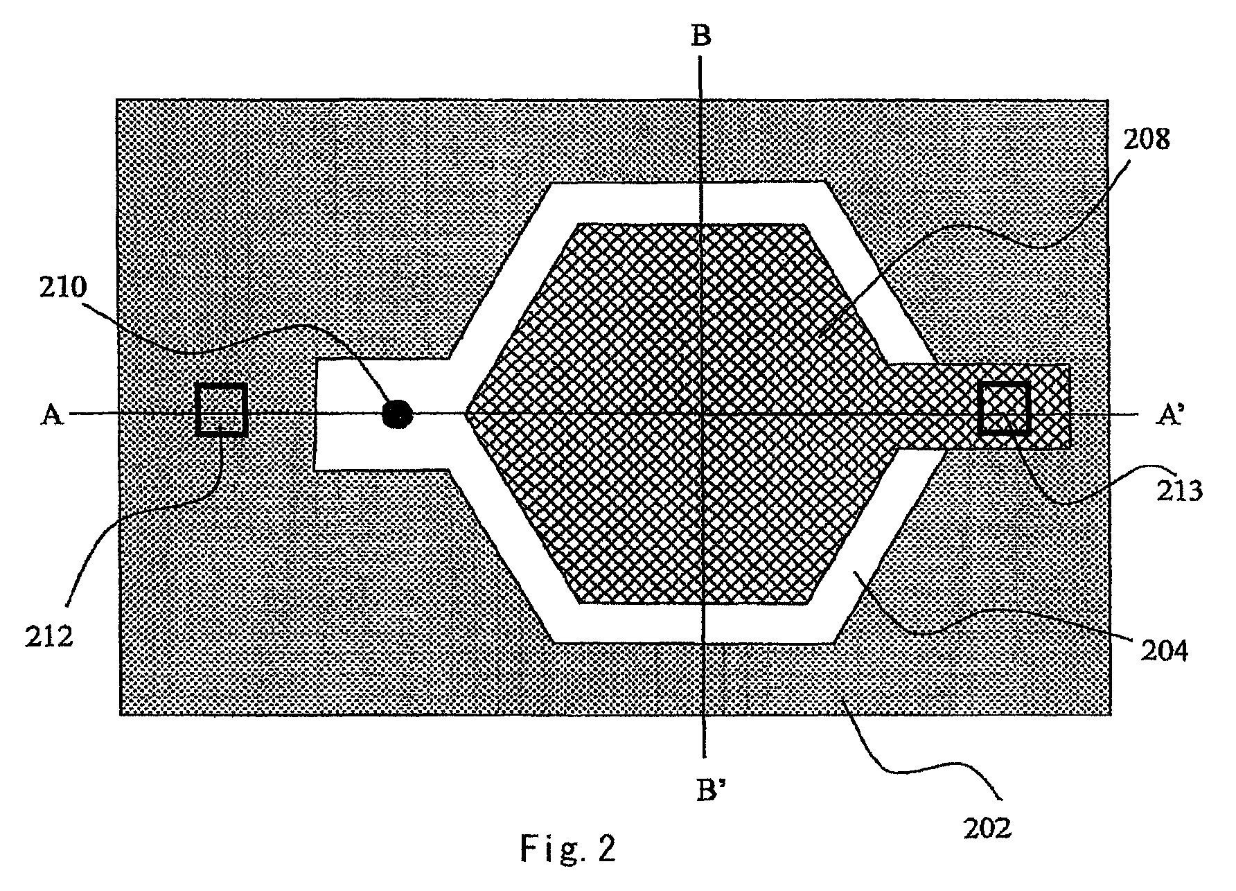
[0069]FIG. 2 is a top view of an ultrasonic transducer (CMUT) according to the embodiment 1. FIG. 2 shows a single CMUT cell. The CMUT cell comprises a lower electrode 202, a hollow part 204 formed above the lower electrode 202, an upper electrode 208 disposed above the hollow part 204, and so forth. An etching hole 210 for forming the hollow part is communicated with a portion to become the hollow part 204. An opening 212 is provided so as to reach the lower electrode 202, and an opening 213 is provided so as to reach the upper electrode 208. Between the lower electrode 202 and the hollow part 204, an insula...

embodiment 2

[0084]Whereas the embodiment 1 is an embodiment in which the conductive film is exposed to the hollow part from the underside of the hollow part, the embodiment 2 is an embodiment in which the conductive film is exposed to the hollow part from the upside of the hollow part.

[0085]FIG. 17 is a top view of an ultrasonic transducer (CMUT) according to the embodiment 2. FIG. 17 shows a single CMUT cell. The CMUT cell is constituted with the lower electrode 202, the hollow part 204 formed above the lower electrode 202, the upper electrode 208 formed above the hollow part 204, and so forth. The etching hole 210 for forming the hollow part is communicated with a portion to become the hollow part 204. The opening 212 is provided so as to reach the lower electrode 202, and the opening 213 is provided so as to reach the upper electrode 208. Between the lower electrode 202 and the hollow part 204, the insulating film 203 consisting of a silicon oxide film is formed so as to cover the lower elec...

embodiment 3

[0091]Although the embodiments 1 and 2 are embodiments in which the conductive film is exposed to the hollow part from either one of the upside and underside of the hollow part, the embodiment 3 is an embodiment in which both a conductive film exposed to the hollow part from the upside thereof and a conductive film exposed to the hollow part from the underside thereof are disposed.

[0092]FIG. 19 is a top view of an example (first example) of ultrasonic transducer (CMUT) according to the embodiment 3. FIG. 19 shows a single CMUT cell as shown for the embodiments 1 and 2, but the shape of the cell of the embodiment 3 is different from those of the cells of the embodiments 1 and 2. The CMUT cell is constituted with the lower electrode 202, the hollow part 204 formed above the lower electrode 202, the upper electrode 208 disposed above the hollow part 204, and so forth. The etching hole 210 for forming the hollow part is communicated with a portion to become the hollow part 204. The open...


PUM


Abstract

In an ultrasonic transducer comprising a first electrode, a first insulating film disposed on the first electrode, a hollow part provided above the first insulating film and disposed between surfaces above and below the hollow part, a second insulating film disposed above the hollow part, and a second electrode disposed on the second insulating film, a first conductive film disposed on a side of the surface below the hollow part and a second conductive film disposed on a side of the surface above the hollow part are provided, the first conductive film and the second conductive film are disposed so that they overlap with a region in which the surfaces above and below the hollow part contact with each other as seen from above when the transducer is driven, and they do not overlap with each other in the region as seen from above.

Description

TECHNICAL FIELD[0001]The present invention relates to an ultrasonic transducer and an ultrasonic diagnostic device using the same. In particular, the present invention relates to an ultrasonic transducer produced by the micro electro mechanical system (MEMS) technology, and an ultrasonic diagnostic device using the same.BACKGROUND ART[0002]Ultrasonic transducers transmit and receive ultrasonic waves, and thus they are used for diagnosis of tumors etc. in human bodies, nondestructive tests of structures, and so forth. As the ultrasonic transducers, those utilizing vibration of piezoelectric substances have so far been used. However, with progress of the MEMS technology in recent years, capacitive micromachined ultrasonic transducers (CMUTs) comprising a vibration part formed on a silicon substrate have been actively developed aiming at practical use thereof. For example, U.S. Pat. No. 6,320,239 B1 (Patent document 1) discloses a single CMUT and a CMUT array.[0003]In contrast to the c...

Claims


Application Information

Patent Timeline
Patent Type & Authority Patents(United States)
IPC IPC(8): A61B8/00
CPCB06B1/0292A61B8/00H02N1/08
Inventor MACHIDA, SHUNTAROTAKEZAKI, TAIICHIMINE, TOSHIYUKI
Owner FUJIFILM HEALTHCARE CORP
Why Eureka
Try Eureka