Hydroponic irrigation system

a technology of hydroponic irrigation and water pump, which is applied in the field of hydroponic irrigation system, can solve the problems of backpressure in the valve cavity, and achieve the effects of less prone to clogging, easy adjustment, and low manufacturing cos

Inactive Publication Date: 2014-01-07
SINGH VIJAY
View PDF18 Cites 10 Cited by
  • Summary
  • Abstract
  • Description
  • Claims
  • Application Information

AI Technical Summary

Benefits of technology

[0007]The present invention relates to a flood control valve and to a simple and low cost hydroponic irrigation system employing that valve. The irrigation system is capable of operating unattended for weeks at a time with little or no maintenance. It is useful both for large commercial applications, as well as hobby and home use. A variety of plants for decorative and food use can be grown in the system. A single feed pump can supply a number of plant cultivation vessels, which can be of different sizes and positioned at different elevations. A feed pump is activated by an automatic electric timer at preset intervals. The pump draws the hydroponic nutrient solution from a reservoir and supplies it through pipes to a flood control valve located on each plant cultivation vessel. The flood control valve has an inlet and an outlet connection for the feed stream, and similar inlet and outlet ports for draining the spent nutrient solution out of the cultivation chamber. The streams are introduced into a cavity in the valve, but kept separated by a flexible rubber membrane. The feed and drain streams are oriented in opposite directions with the feed stream allowed to flow up through the valve into the cultivation chamber, and the drain stream allowed to flow downwards by gravity. When feed is not flowing through the valve, the flexible membrane is in a relaxed state and centered in the cavity. This orientation permits fluid to drain downwards out of the valve. However, when the feed pump is turned on it pushes nutrient solution upwards through the valve. The flow results in backpressure in the valve cavity and this backpressure causes the flexible membrane to expand and push towards the drain side of the cavity. This expansion of the membrane effectively blocks off the drain side and no liquid can drain out of the valve. This permits the cultivation chamber to fill up rapidly and without wastage. Once the fill cycle is completed, usually set by a timer, the feed pump turns off, backpressure rapidly decays and the flexible membrane returns to the center of the cavity causing spent liquid to start draining out of the cultivation chamber. This design has essentially no moving parts (apart from the flexing of a rubber membrane) and operates automatically without the need for any power. A positionable overflow tube is provided in the valve and can be moved up and down to set the desired height of the nutrient solution in the cultivation chamber during the flooding phase of the cycle.
[0014]It is still a further object of embodiments of the present invention to provide a flooding control valve that is self-cleaning as each cycle compresses and forces any accumulated debris out of the valve cavity.

Problems solved by technology

The flow results in backpressure in the valve cavity and this backpressure causes the flexible membrane to expand and push towards the drain side of the cavity.

Method used


Image

  • Hydroponic irrigation system
  • Hydroponic irrigation system
  • Hydroponic irrigation system

Examples


Embodiment Construction

[0023]Exemplary embodiments are discussed in detail below. While specific exemplary embodiments are discussed, it should be understood that this is done for illustration purposes only. In describing and illustrating the exemplary embodiments, specific terminology is employed for the sake of clarity. However, the embodiments are not intended to be limited to the specific terminology so selected. Persons of ordinary skill in the relevant art will recognize that other components and configurations may be used without departing from the true spirit and scope of the embodiments. It is to be understood that each specific element includes all technical equivalents that operate in a similar manner to accomplish a similar purpose. Therefore, the examples and embodiments described herein are non-limiting examples.

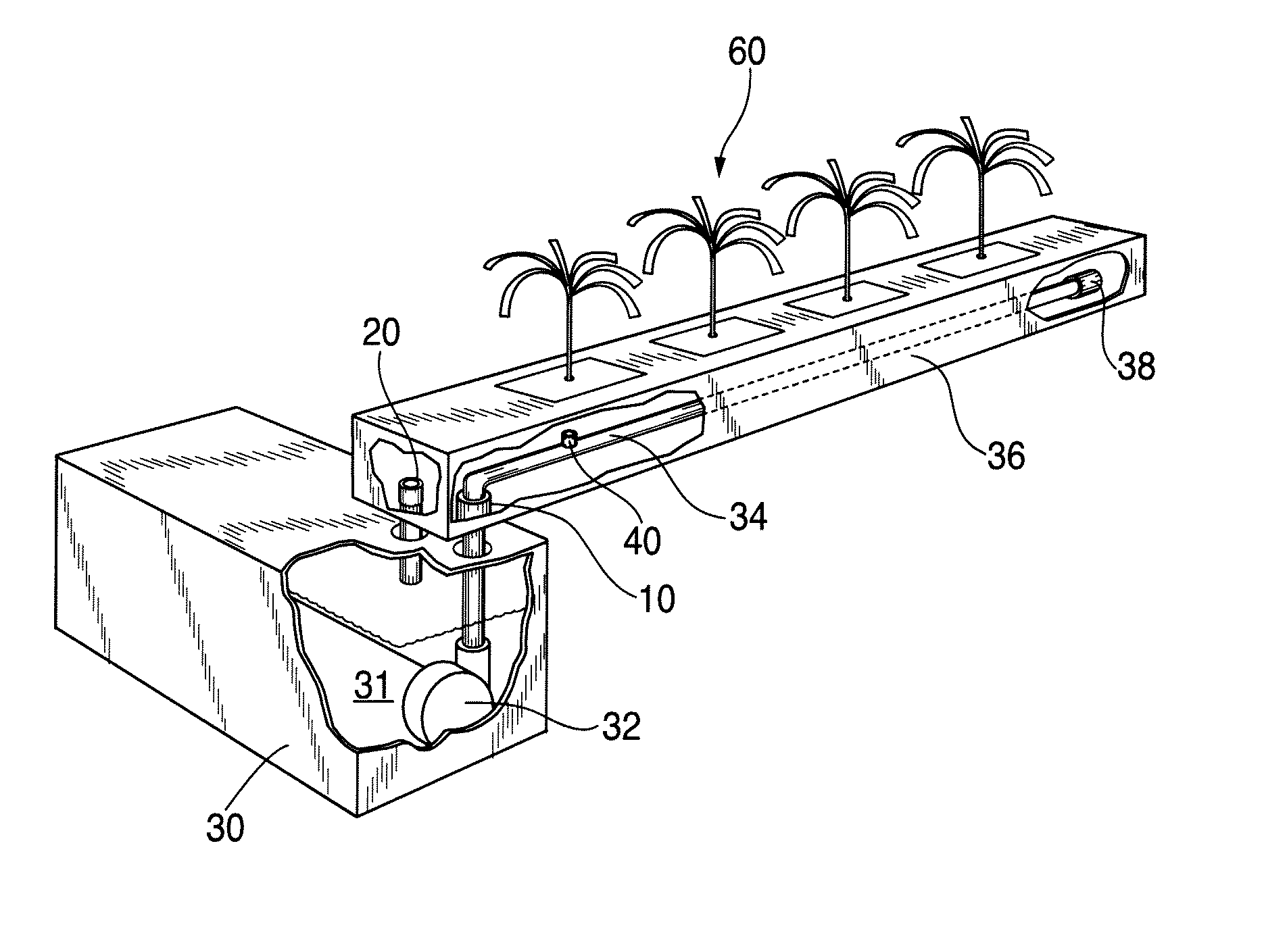
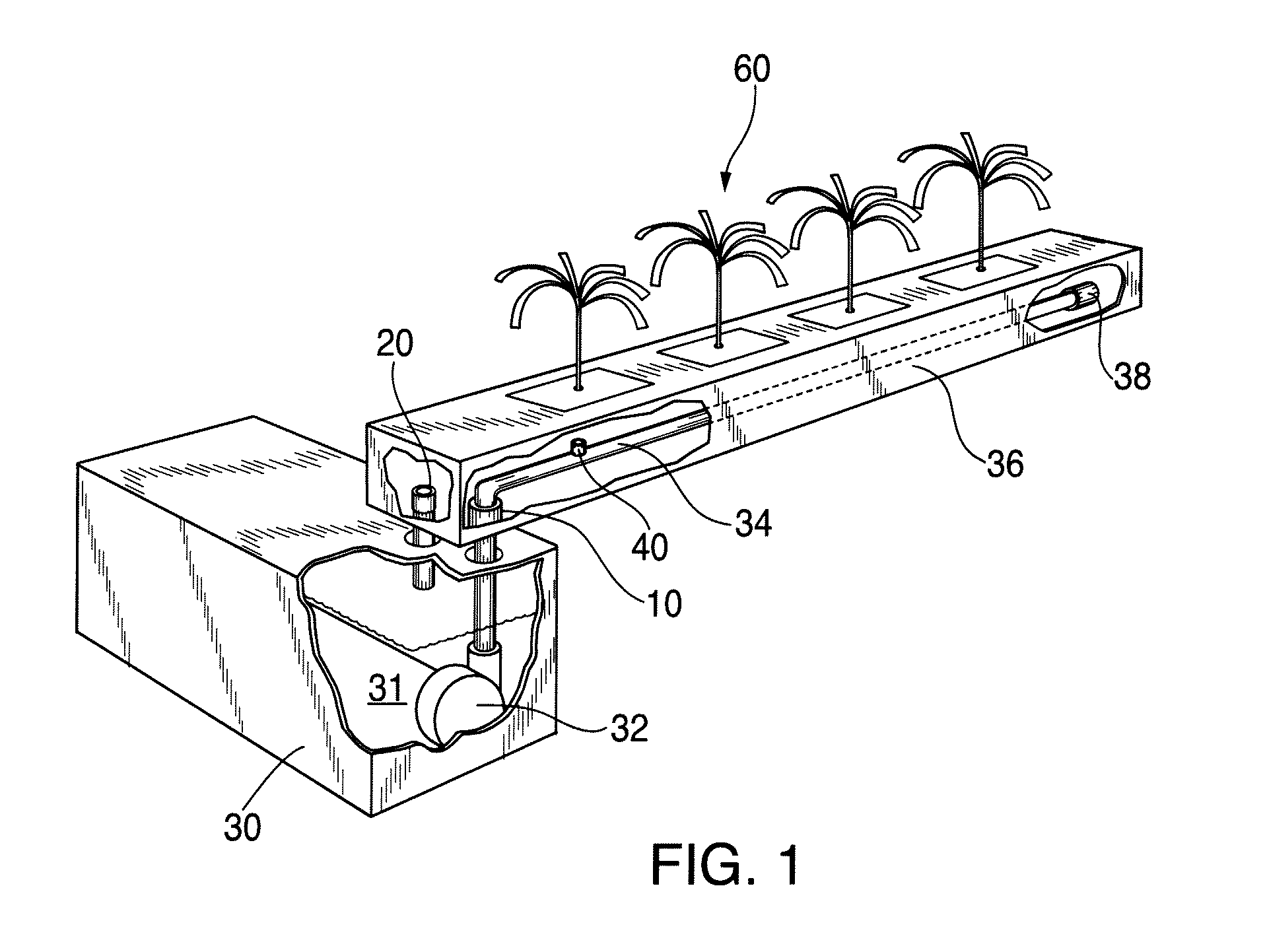
[0024]Referring now to the drawings, wherein like reference numbers generally indicate identical, functionally similar, and / or structurally similar elements, there is shown in FIG. 1...


PUM


Abstract

A low cost valve and system for automated ebb and flow irrigation utilizes a collapsible sleeve to control fluid flow direction. No external power, moving parts, or floats are needed to operate the valve, resulting in improved reliability, low operating cost, and minimal need for maintenance. The valve operates using feed pressure to close the drain when hydroponic nutrient solution is pumped into the cultivation chamber. The valve drains automatically once the pump is stopped, usually by means of a timer, and the spent hydroponic solution is recovered. The fill / drain cycle is repeated as needed to keep the plants moist, yet not waterlogged.

Description

BACKGROUND OF THE INVENTION[0001]1. Field of the Invention[0002]The present invention relates generally to valves for controlling the intermittent flooding or flushing of liquids into a vessel, and more particularly to apparatus for controlling the circulation of hydroponic solutions to and from cultivation containers for plants.[0003]In hydroponic culture, a common mode of operation is termed “ebb and flow”. In this operation, plants are contained in a culture vessel and the roots are intermittently flooded with a nutrient solution, and then the solution is allowed to drain out. It is important that this “ebb and flow” operation be automated and functions reliably. If the plants roots are not flooded in time, they will dry out resulting in irreparable damage to the plant roots. On the other hand if the hydroponic solution stagnates in the cultivation container, then the roots will rot, again causing irrecoverable damage. In addition to reliable operation, it is essential that the d...

Claims


Application Information

Patent Timeline
Patent Type & Authority Patents(United States)
IPC IPC(8): A01G31/02
CPCA01G31/02Y02P60/21
Inventor SINGH, VIJAY
Owner SINGH VIJAY
Why Eureka
Try Eureka