Suspension system

a suspension system and suspension technology, applied in the direction of machine supports, transportation and packaging, other domestic objects, etc., can solve the problems of limited suspension performance, noisy hydraulic active seat suspension, bumpy or uncomfortable ride of operators,

Active Publication Date: 2014-01-07
DEERE & CO
View PDF52 Cites 8 Cited by
  • Summary
  • Abstract
  • Description
  • Claims
  • Application Information

AI Technical Summary

Benefits of technology

[0003]Accordingly, an object of this invention is to provide a seat suspension system which is quiet and is capable for being actively controlled.
[0004]A further object of the invention is to provide such a seat suspension system which does not require high pressure hydraulic lines to enter or exit the operator cab.

Problems solved by technology

As a result, the operator may experience a bumpy or uncomfortable ride.
While significantly improving the ride by actively controlling seat top velocity, the suspension performance is limited by the response speed of the hydraulic system, including the control valve.
Additionally, a hydraulic active seat suspension can be noisy due to the hydraulic fluid flow.
Such a system also requires high pressure hydraulic lines to enter / exit the operator cab, consumes significant power over the minimum required by the suspension due to the pressure reducing valve, and must be “tuned” to the ride performance of individual vehicles, which requires hardware changes to the hydraulic control valve.

Method used


Image

  • Suspension system
  • Suspension system
  • Suspension system

Examples


Embodiment Construction

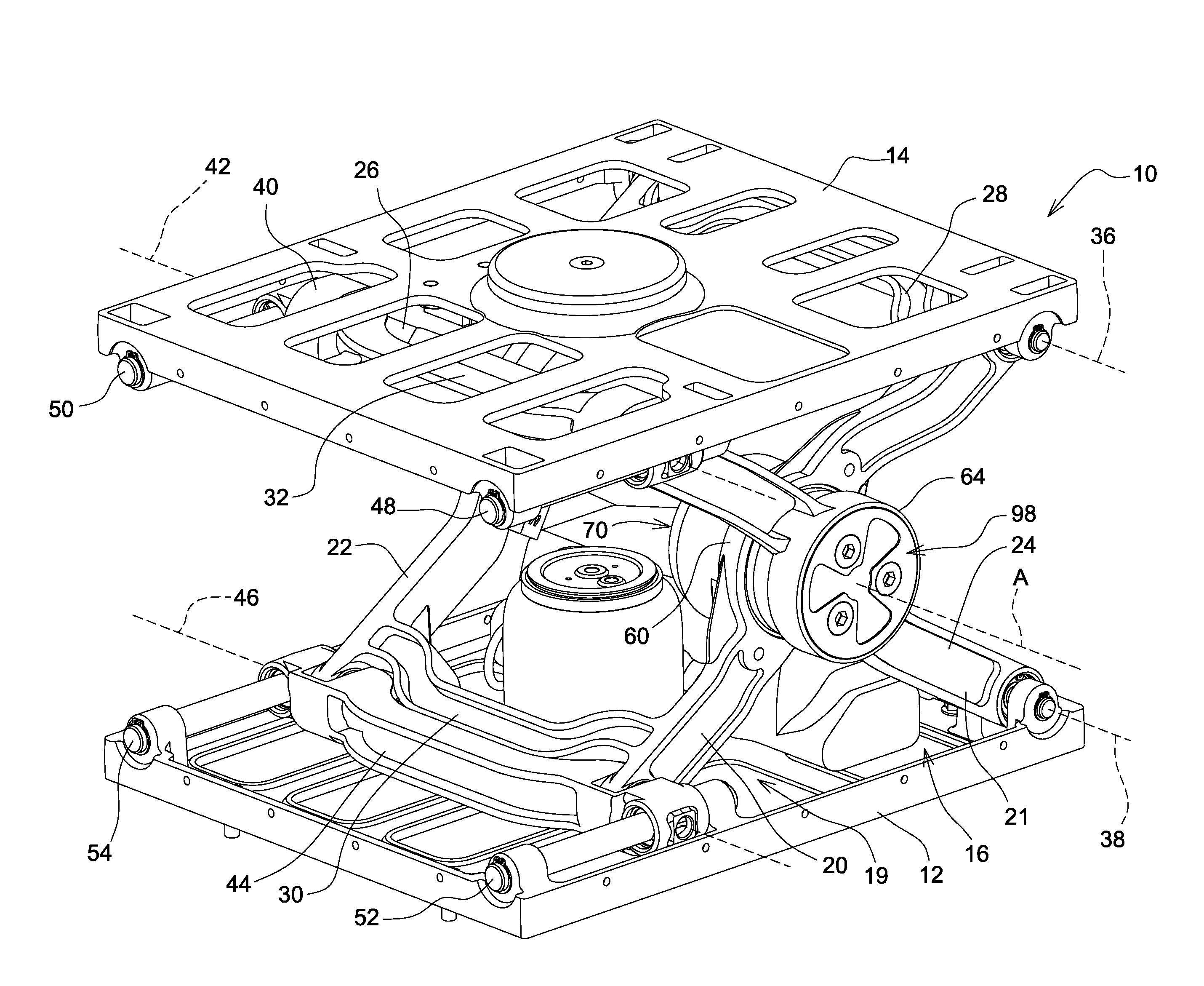
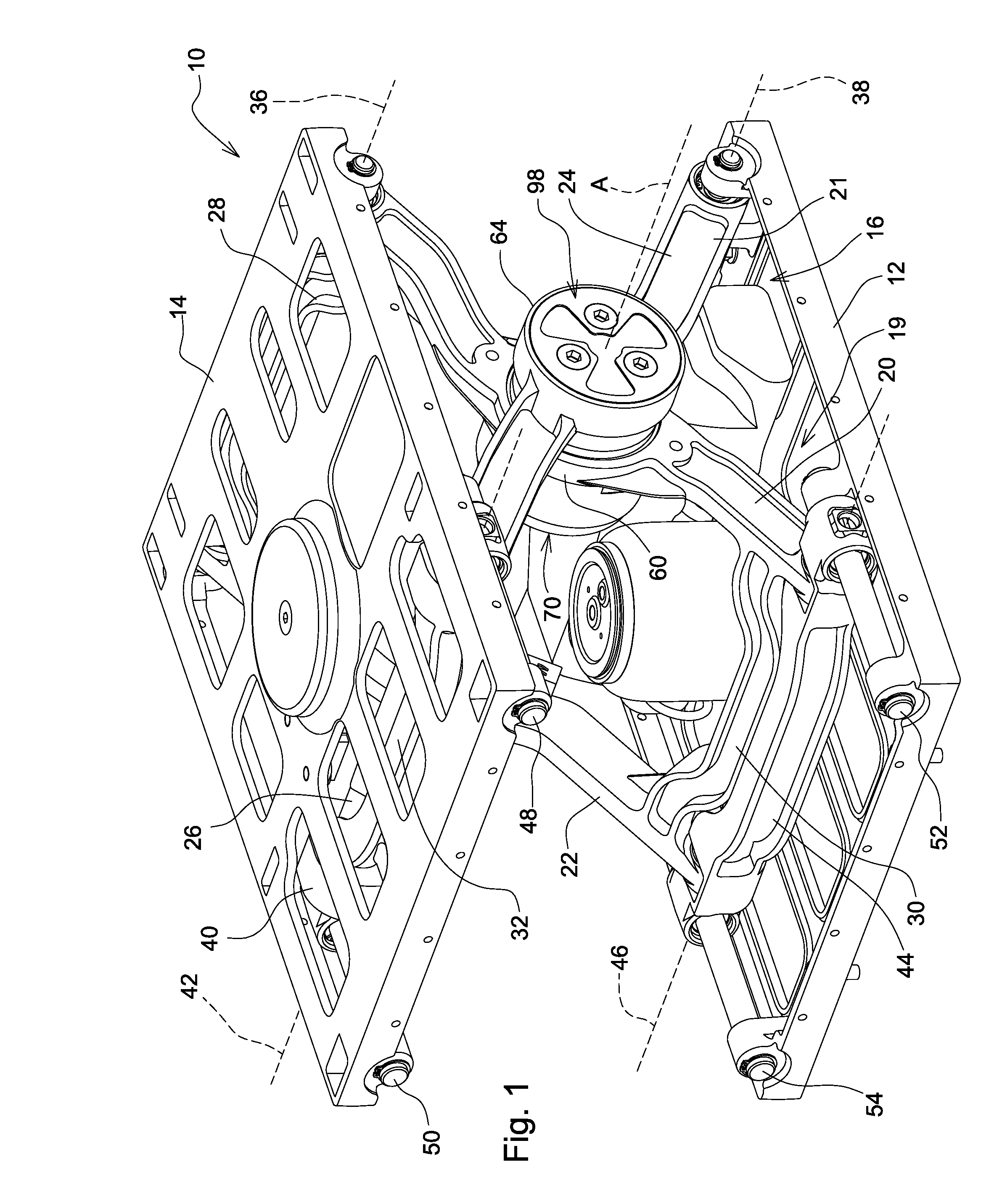
[0010]Referring to FIG. 1, the suspension system 10 includes a base frame 12 for mounting on a vehicle chassis (not shown) and seat carrier frame 14 which is adapted to support a seat assembly (not shown). The carrier frame 14 is supported with respect to the base frame 12 by a linkage 16, preferably a scissors linkage.

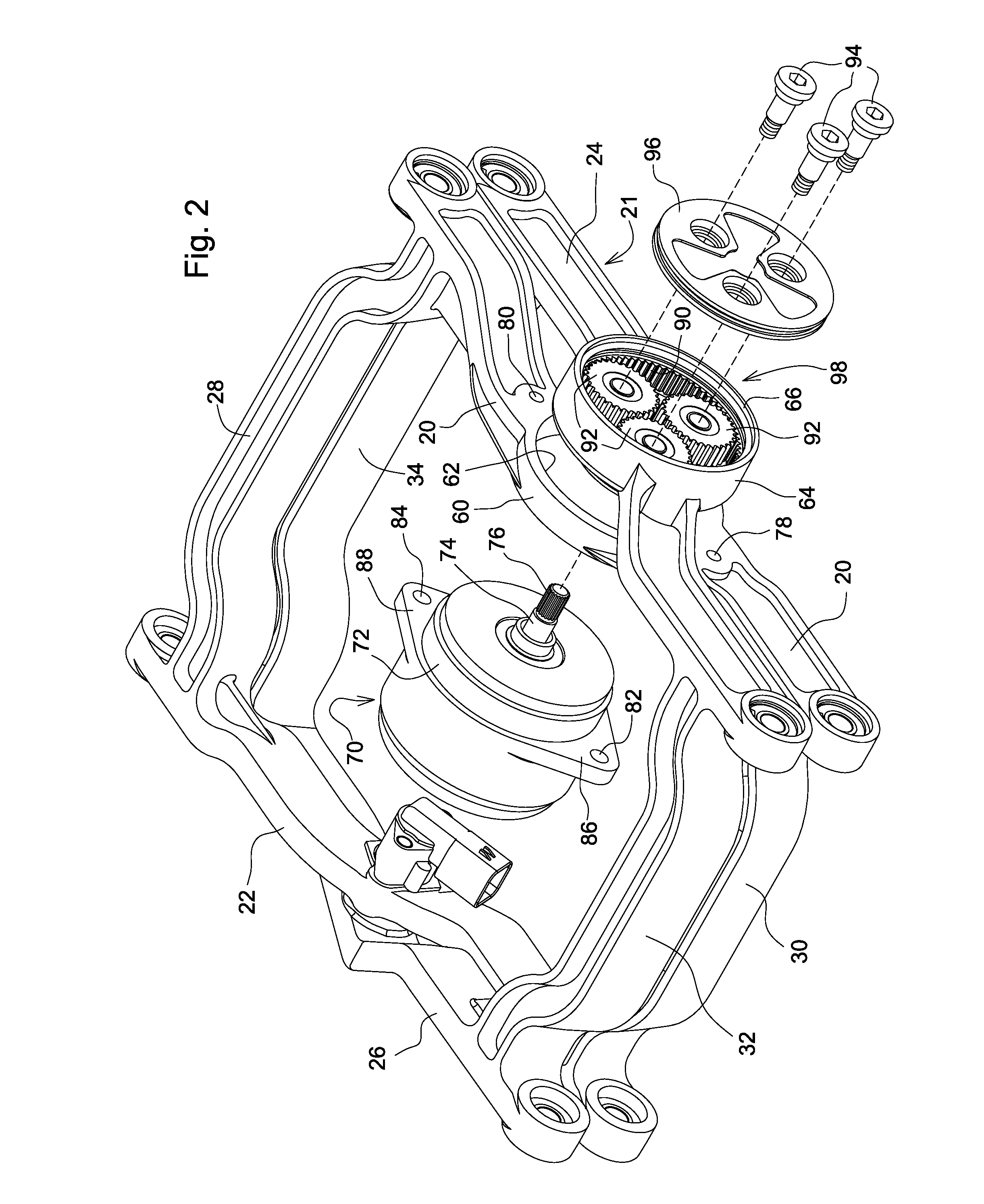
[0011]The linkage 16 includes a first link 19 with a pair of first arms 20 and 22, and a second link 21 with a pair of second arms 24 and 26. First arms 20 and 22 are interconnected by an upper cross arm 28 and a lower cross arm 30. Second arms 24 and 26 are interconnected by an upper cross arm 32 and a lower cross arm 34.

[0012]The upper ends of first arms 20 and 22 are pivotally coupled to one end of carrier frame 14 at a pivot axis 36. The lower ends of second arms 24 and 26 are pivotally coupled to one end of base frame 12 at a pivot axis 38.

[0013]The upper ends of second arms 24 and 26 are pivotally coupled to an upper slide member 40 at a pivot axis 42. The lower...


PUM


Abstract

A suspension system includes a base frame, a carrier frame and a linkage mounted on the base frame and supporting the carrier frame. The linkage includes a first arm pivotally coupled to the frames and a second arm pivotally coupled to the frames and pivotally coupled to the second arm about a linkage pivot axis. A rotary motor has a housing and a shaft which rotates with respect to the housing. The shaft is aligned with the linkage pivot axis. The housing is non-rotatably coupled to the first arm. The shaft is coupled to a transmission which is coupled to the second arm.

Description

FIELD OF THE INVENTION[0001]The present invention relates to a suspension system, such as for an active seat suspension system.BACKGROUND OF THE INVENTION[0002]Agricultural and construction equipment must often be driven over rough terrain. As a result, the operator may experience a bumpy or uncomfortable ride. To minimize the roughness of the operator's ride, operator seats have been equipped with a suspension—typically a passive system consisting of an air spring and hydraulic damper. To improve the ride, active seat suspension systems have been used wherein the hydraulic damper is replaced with a hydraulic cylinder. While significantly improving the ride by actively controlling seat top velocity, the suspension performance is limited by the response speed of the hydraulic system, including the control valve. Additionally, a hydraulic active seat suspension can be noisy due to the hydraulic fluid flow. Such a system also requires high pressure hydraulic lines to enter / exit the ope...

Claims


Application Information

Patent Timeline
Patent Type & Authority Patents(United States)
IPC IPC(8): F16M13/00
CPCB60N2/502B60N2/509B60N2002/024B60N2/508B60N2/501B60N2/02258
Inventor KEEN, ERIC, A.
Owner DEERE & CO
Why Eureka
Try Eureka