Terminal fitting and electric wire equipped with the same

a technology of terminal fittings and electric wires, applied in the direction of multi-conductor cable end pieces, coupling contact members, coupling device connections, etc., can solve the problems of easy deformation of crimping portions, easy entry of anti-corrosion agents dropped or spraying from above the terminal fittings into the gap between the crimping portion and the coated electric wires, and avoid electric corrosion. , to prevent the occurrence of electric corrosion

Inactive Publication Date: 2014-01-07
AUTONETWORKS TECH LTD +2
View PDF17 Cites 43 Cited by
  • Summary
  • Abstract
  • Description
  • Claims
  • Application Information

AI Technical Summary

Benefits of technology

[0009]In this configuration, when an anti-corrosive agent is applied after the coated electric wire is crimped and fixed to the terminal fitting, the anti-corrosive agent enters an opening of the lead-in groove in the coupling portion. In this context, even when the coated electric wire is in close contact with the coupling portion of the terminal fitting, the anti-corrosive agent can enter the site below the coated electric wire at the coupling portion through the lead-in groove. Then, the anti-corrosive agent fills the lead-in groove to thereby form an anti-corrosive wall along the lead-in groove, that is, in a direction intersecting with the axial direction of the coated electric wire, in a manner to enclose the outer circumferential portion of the coated electric wire. Moreover, even when there is a gap partially between the coupling portion and the coated electric wire, the gap is filled with the anti-corrosive agent spilt over from the lead-in groove. In such a manner, the gap between the coated electric wire and (the lead-in groove in) the coupling portion can be securely filled with the anti-corrosive agent to prevent water content from entering from the side of the insulation barrel to the side of the wire barrel. Therefore, this configuration prevents the occurrence of electric corrosion.
[0010]According to the present invention, it is possible to prevent the occurrence of electric corrosion at a portion where the terminal fitting and the electric wire come in contact with each other.

Problems solved by technology

When the coated electric wire is electrically connected to the terminal fitting, in a case where the core wires of the coated electric wire and the terminal fitting are made of different kinds of metals, if water exists at a portion where the two come in contact with each other, it is known that the metals both dissolve in water in the shape of ions to give rise to electric corrosion in which corrosion makes progress by electrochemical reaction.
In a configuration where the coated electric wire is electrically connected by crimping the coated electric wire at the crimping portion of the terminal fitting, it is difficult to deform the crimping portion into a shape completely conforming to the outer circumferential portions of the coated electric wire and the core wires.
As a result, an anti-corrosive agent dropped or sprayed from above the terminal fitting may not easily enter the gap between the crimping portion and the coated electric wire as well as core wires.

Method used


Image

  • Terminal fitting and electric wire equipped with the same
  • Terminal fitting and electric wire equipped with the same
  • Terminal fitting and electric wire equipped with the same

Examples


Embodiment Construction

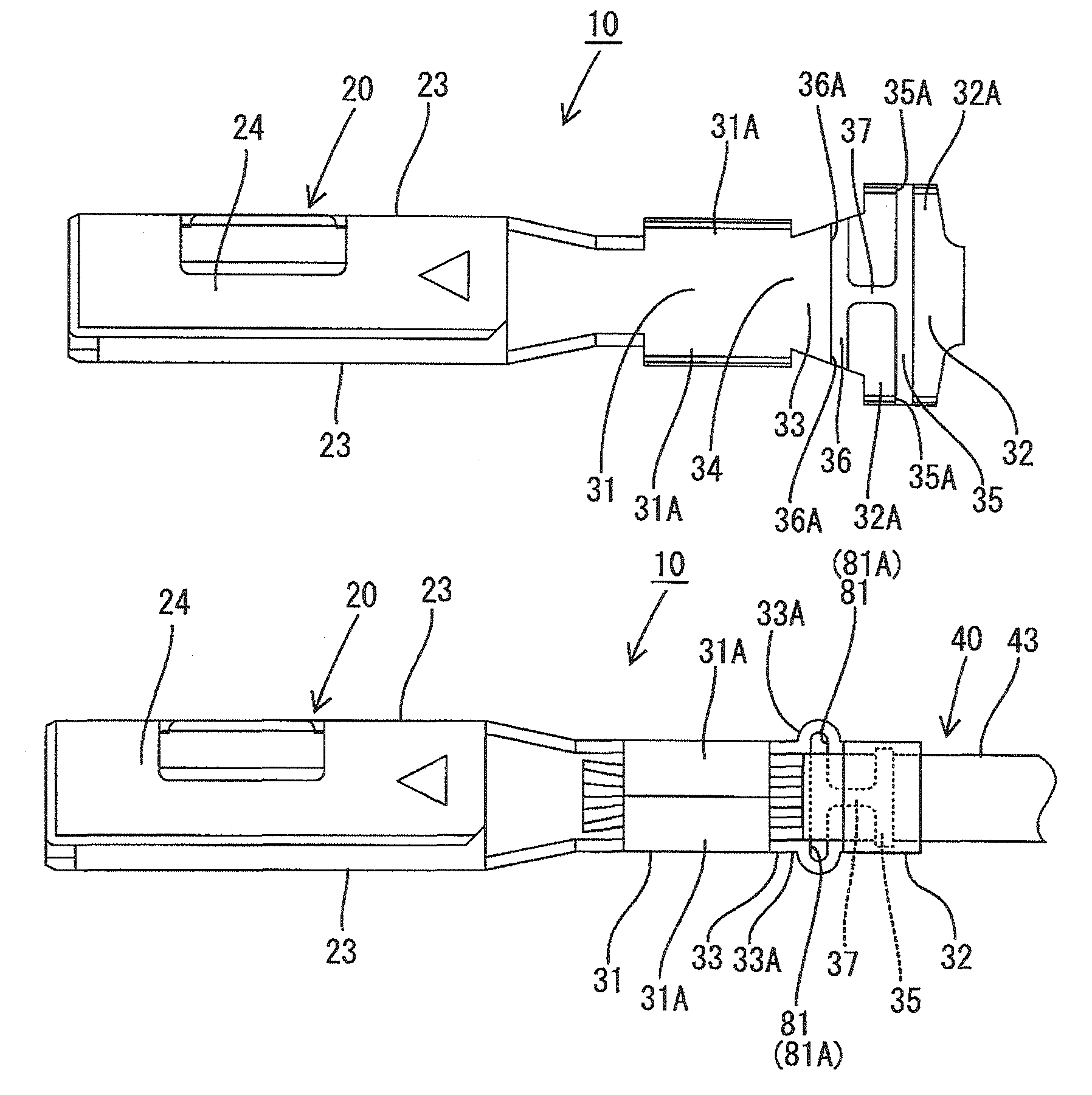
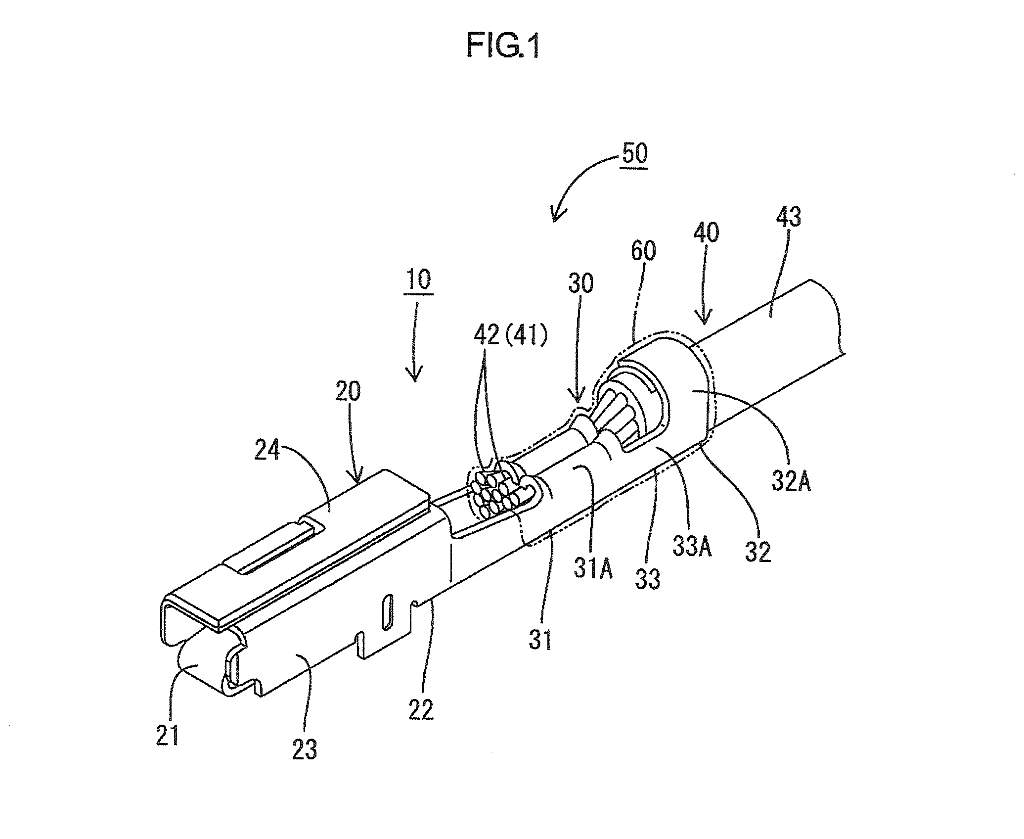
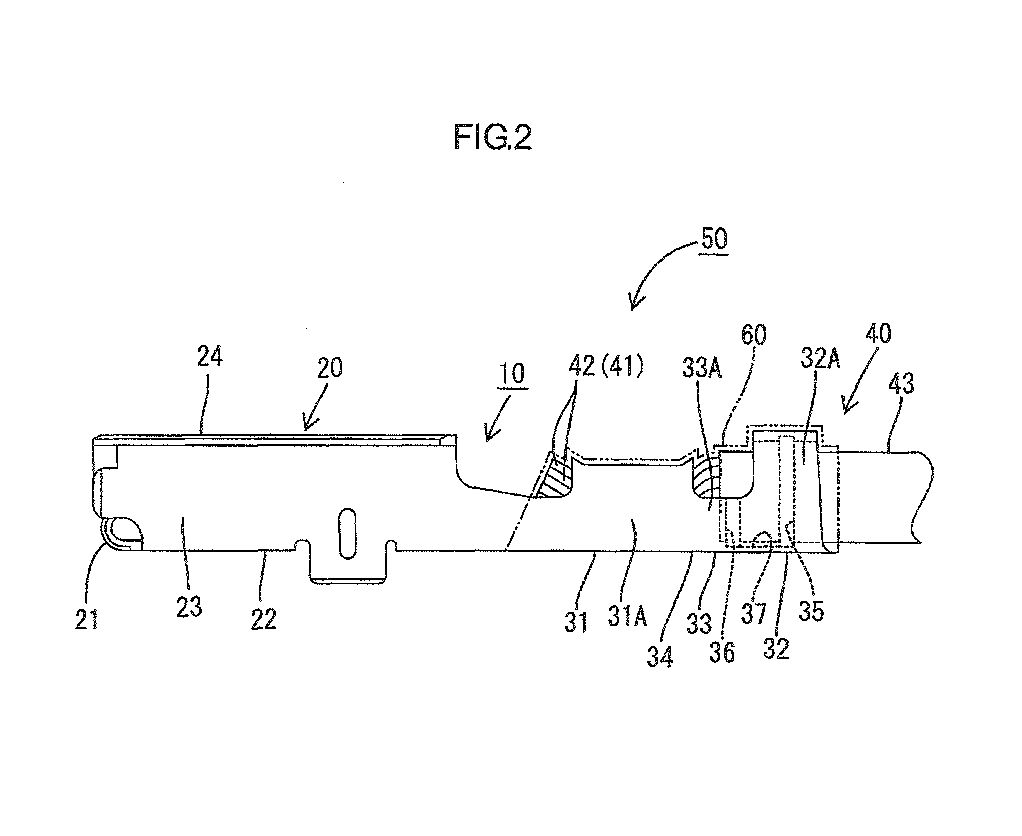
[0023]A first embodiment of the present invention will be described with reference to FIGS. 1 to 8. A terminal fitting 10 in the present embodiment is made of copper alloy and as shown in FIGS. 1 and 2, includes a square-tubular body portion 20 and a crimping portion 30 provided in the rear of the body portion 20. The terminal of a coated electric wire 40 is crimped to the crimping portion 30 to configure an electric wire equipped with terminal fitting 50 as a whole. To the crimping portion 30 and a site of the coated electric wire 40 that is fixed to the crimping portion 30, an anti-corrosive agent 60 is applied. The anti-corrosive agent 60 that is undiluted is dropped or sprayed from above the terminal fitting 10 after the coated electric wire 40 is crimped and fixed to the crimping portion 30 and left as it is for a predetermined time to become solidified. Although in the present embodiment, the terminal fitting 10 is exemplified as a female terminal fitting having the body porti...


PUM


Abstract

A terminal fitting 10 having a wire barrel 31 crimping the terminal of an exposed core wire 42 of a coated electric wire 40, an insulation barrel 32 provided in the rear of the wire barrel 31 and fixing the coated electric wire 40, and a coupling portion 33 coupling the wire barrel 31 and the insulation barrel 32 to each other. The coupling portion 33 having a surface coming in contact with the coated electric wire 40 has a lead-in groove 36 to introduce an anti-corrosive agent. The lead-in groove extends in a direction intersecting with the axial direction of the coated electric wire 40 such that at least one of end portions is opened at the side edge of the coupling portion 33.

Description

BACKGROUND OF THE INVENTION[0001]1. Field of the Invention[0002]The present invention relates to a terminal fitting connected to an electric wire and an electric wire equipped with the terminal fitting.[0003]2. Description of the Related Art[0004]Conventionally, one described in, for example, Japanese Unexamined Patent Publication No. 2005-339850 has been known as a terminal fitting connected to the terminal of an electric wire. The terminal fitting has a body portion connected with a mating conductor and, in the rear of the body portion, a crimping portion at which the terminal of a core wire in the coated electric wire is crimped and fixed.[0005]When the coated electric wire is electrically connected to the terminal fitting, in a case where the core wires of the coated electric wire and the terminal fitting are made of different kinds of metals, if water exists at a portion where the two come in contact with each other, it is known that the metals both dissolve in water in the sha...

Claims


Application Information

Patent Timeline
Patent Type & Authority Patents(United States)
IPC IPC(8): H01R4/18H01R4/10
CPCH01R4/185H01R13/03H01R13/114
Inventor MORIKAWA, SATOSHIKOBAYASHI, KAZUMASAOTSUKA, TAKUJISHIMODA, HIROKI
Owner AUTONETWORKS TECH LTD
Why Eureka
Try Eureka